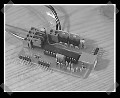
[Ian] put up his RGB LED color changer project over at diylife. It’s a pretty simple project, but well designed and flexible for combining with other projects. He used a PIC18F2550 to drive everything, and some FETs to drive the LEDs. When you connect a USB cable, the color cycling project stops and the PIC responds to simple hex based color commands.


8 thoughts on “RGB PIC Color Changer”
Leave a Reply to 8WayCancel reply
Please be kind and respectful to help make the comments section excellent. (Comment Policy)


How the hell did he interface to USB so easy?
the PIC18F2550 has integrated usb 1.1.
The 18F2550 is a USB PIC. It’s really easy to get a USB connection working with it.
I’ve used the 18f4550, which it’s 40-pin big brother a lot. Here’s some info on it:
http://eegeek.net/content/view/13/32/
The part with schematic drawing on whiteboard was funny to see.
Less spectacular, my RGB decorated mouse with PIC16F84…
http://www.youtube.com/watch?v=UufFRRQs1P0
http://flickr.com/search/?q=razer&w=13006157%40N00
The 18F2550 actually has full-speed USB 2.0. (Not High-Speed, obviously)
comment i left on the diylife board:
Nice design. I wonder if you get subtle flickers when updating the PWM values. I’ve found in my designs on the 14bit pics, that I have to update the PWM when my ” 1 byte cycle counter” wraps to zero rather than immediately. You are clocking at a higher clock rate (I use 4-8mhz internal clocks with up to 10 PWM channels), so your design may not be so sensitive.
Recently, i’ve given up on the PIC and it’s goofy architecture and moved to the Cypress PSOC parts. They are really neat with dedicated digital and analog blocks. You can set up up to 16 PWM (actually I use pseudo random bit sequences, which have less flicker) outputs, and the C compiler is really reliable vs the buggy stuff i’ve experienced w/ the pic (though the PSOC compiler generates crap code). The PSOC has it’s own shortcomings, such as a really inefficient CPU, but the digital and analog blocks more than make up for it b/c stuff is done in HW vs SW. PSOC is really fun, esp when u wrap your head around it’s way of doing things.
Check out this RGB LED Project,
RGB LED Array,…
the RGB LED Project
http://rgb.kitiyo.com