In part 1 we showed you how to build your own prototype RGB keypad. Today we’ll show off some new ideas we worked on to create the project and turn it from prototype to fully functional battle station er door lock.
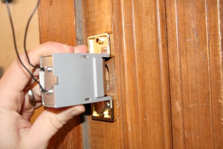
To replace the old door strike with our new electric unit, we had to align it with the old one. Once it was set, we traced around the mounting plate with a pen and got to work. We grabbed a 3/8 inch bit and drilled out the width and depth of the hole to match the body of the strike. Then we cleaned up things a bit with a wood chisel until the hole was just big enough. The strike requires 12 volts to release, so we had to feed some wire to it. We dug up a fairly long drill bit and drilled through the wall and into the strike mounting hole.
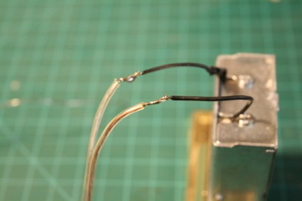
The strike wiring is low voltage, so the wire doesn’t have to be anything special. We used some 18 gauge speaker wire – it’s cheap and we already had it in our parts bin. Pulling the wire is pretty easy. Just feed the wire through and grab the end with a pair of needle nose pliers. Since we had 50 feet of wire to work with, we pulled the wire over to our bench and did a quick soldering job to the strike leads. Once the connections were solid, we insulated them with electric tape. There’s no polarity to worry about, so just get things connected and ready to rock.
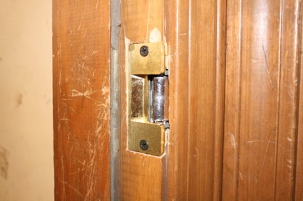
The strike has a thick mounting flange, so we had to remove some wood from the surface of the door frame. After some quality time with a hammer, flat headed screw driver, and a wood chisel, we managed to cut a decent mounting slot. Once the wiring was insulated, we pulled in the slack and mounted the strike with a pair of three inch screws.
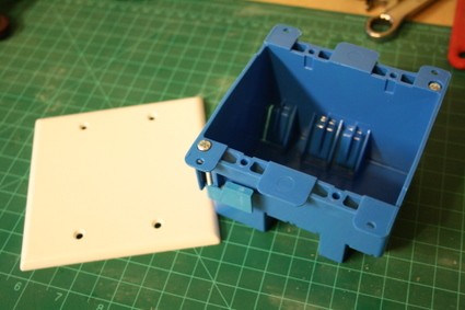
We’ll be wall mounting the keypad, so we picked up an “old-work” two gang electrical box and a two gang blank wall plate. Mounting the box is pretty easy, but we’ll walk you through it.
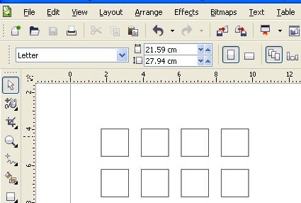
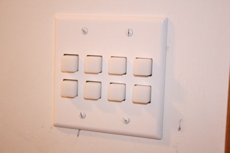
To make the bezel, we laid out the buttons in CorelDraw and scaled up each button by a few percent. Once the size was correct, we rounded off the corners to match the buttons better.
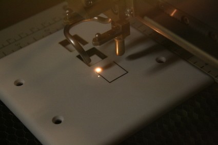
After a few test fits made by cutting paper, we put the wall plate into our ever handy laser cutter. We realize that most of you don’t have one of these awesome machines – you can create your own with some careful drilling and dremel work (it might be easier to bribe the local sign shop with some beer). If you do have it laser cut, make sure you get a nylon wall plate and not a PVC plate. The fumes from burning PVC are toxic and air filters will not neutralize them.
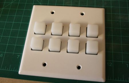
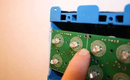
When we test fit the new bezel, we found that the flex at the base of each button was impeded. It’s hard to see here, but the wall plate is only about 1/32 of an inch thick. Since it’s so thin, the buttons stick out too far.
![]()
To solve both problems, we created a sub-bezel. We used the same laser template, but expanded each hole a bit further. The 1/8 inch acrylic provided perfect depth for the buttons and the larger holes in the sub-bezel provide an area for the buttons to flex.
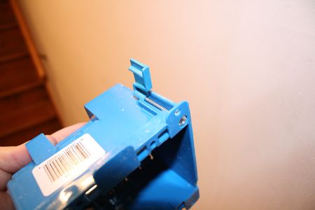
“Old-work” boxes are designed to be installed into existing drywall. You just have to cut a hole for the box and when the screws are tightened, these tabs will flip up to grip the inside of the wall.
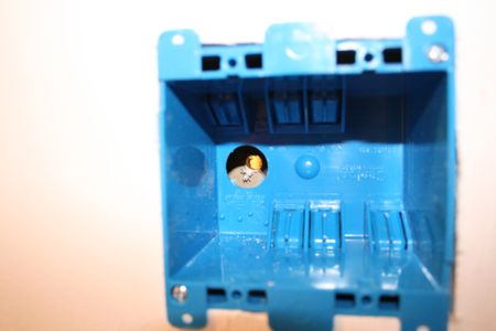
Once the hole’s cut, just insert the box and check the fit. Don’t tighten the screws just yet – we’ll be pulling it back out for a quick mod. Since we’re mounting all the hardware on the other side of the wall, we drilled a hole into the workshop side to run the keypad wiring.
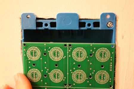
It just happens that Spark Fun’s PC Board is the same width as the 2 gang box. In order to fit the bezel flush, we need to trim back the edge of the box.
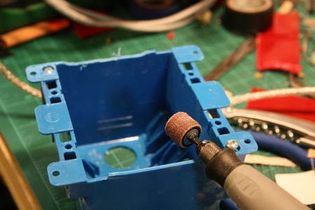
You can use your favorite tool, but we grabbed our rotary tool and a small drum sanding bit. Then we ground the edge of the box down to allow for approximately two times the thickness of the keypad PC board. (You might want to adjust this depending on your bezel design.)
The final fit is just about perfect. The edges of the drywall keep the board from shifting while the box supports the board from behind.
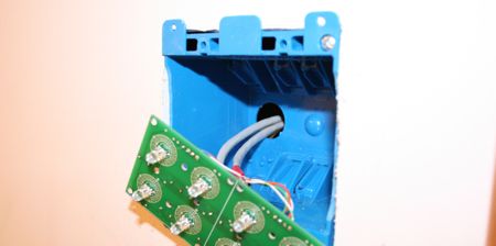
Now that the bezels are ready to go, mark your wiring so you can identify it post install. We used some colored electrical tape and noted the connections. Since we used Cat-5, you could easily use RJ-45 connectors to add some modularity. We didn’t need it, so we just pulled the wires through to the workshop side.
To finish up the key pad, we installed the PC board, the keypad, the acrylic sub-bezel, and finally the keypad. Everything actually floats under the keypad. The design has worked perfectly for the past few months – with one exception. One visitor pushed too hard and popped the PC board back into the wall box. If needed, you can add a support strut of some kind behind the PC board.
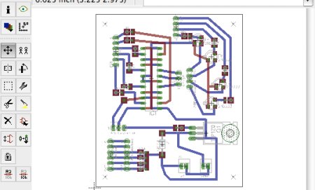
To create a permanent board for the keypad, we laid everything out in Eagle. Since we wanted to try out some interesting etching ideas, we used extra wide traces and expanded the pads to provide plenty of copper.
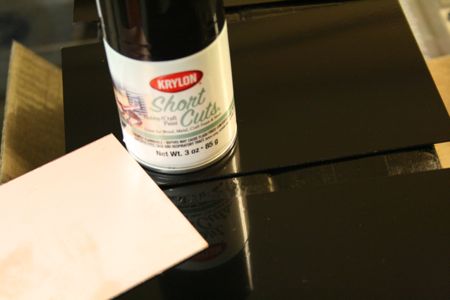
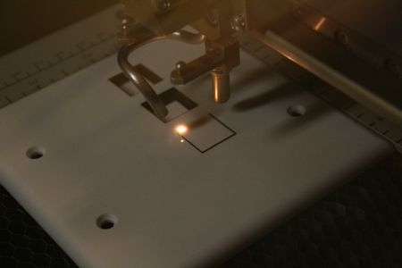
After making the keypad bezel, we wanted to try some new tricks with the laser cutter. We coated some copper clad PC Boards with spray paint and let it harden for a few days.
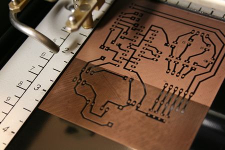
To We exported the design from eagle and sent it to the Epilog via CorelDraw. In order to remove all of the paint, we had to run the etching jo
b twice on the laser. Here, the laser is mid way through the second run.

Even after two jobs, a fine residue was still on the copper. Lightly scrubbing the board with acetone (nail polish remover) removed the left over residue. The traces remained intact and the copper was bared for the etching solution.
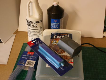
Radio Shack doesn’t bother to carry ferric chloride anymore, but we wanted local chemicals. We picked up some muriatic acid (hydrochloric acid), hydrogen peroxide, a cereal container air pump, bubble block, and some hose. The acid is readily available at the hardware store. We suggest finding the smaller container – it’s the perfect amount for a one time fill.
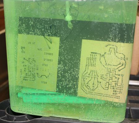
Etching the board is the usual show. The bubbles help agitate the solution around the copper and speed up the process.
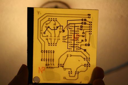
The finished etch came out pretty decent, if slightly over-etched. Holding the board up to a light is an easy way to check for top/bottom layer alignment. The board was slightly over-etched, but after spending a couple of weeks mucking around with the process, we decided that it was time to get on with it already.
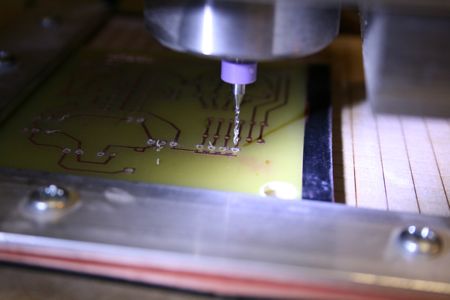
To drill the board, we used a #59 tungsten carbide drill bit. Instead of a drill press, we manually ran our CNC mini mill to drill the board. We only broke one bit and that was when we fat-fingered a direction key.
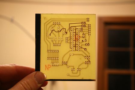
One more quick check and the board looks perfect. The milling machine made it easy to keep the holes in line for the build.
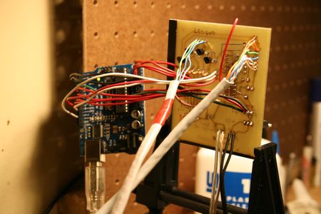
Finishing the build is pretty easy (the red wire going over the board was a quick design fix). We added jumpers for all of the Arduino connections and soldered the Cat-5 from the keypad directly to the new board. We won’t bore you with step by step soldering pics. If you prototyped the circuit, you should be intimately familiar with the thing by now. If you need some help soldering, be sure to check out our introduction to soldering.
The bezel’s built, the PC Board etched, the circuit soldered, and the keypad’s installed. The only thing left to do is enjoy the new keypad… or develop more code and teach it some new tricks.
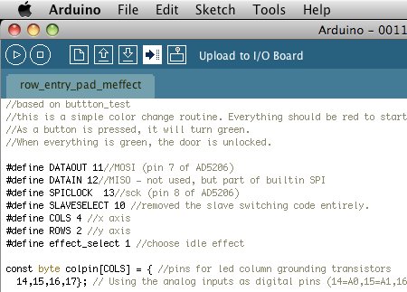
We promised to explain the code a bit, so we’ll give you a quick walk through. The meffect keypad code (available here) was written to simplify the keypad routines for the project. The first several lines initialize the various variables we’ll need to make things work. We added comments regarding pin assignment to help simplify wiring and help people change things around as needed.
The code to drive the digital potentiometer comes directly from this tutorial.
The setup() function is run one time when the controller is powered on or reset. Variables are set and i/o pins are set to their initial states as needed.
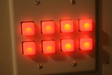
The loop() function is the never ending loop where the controller will perform a few tasks. The main order of business is to read the button states for input. Second, the potentiometers are set and each LED is lit temporarily, based on the values in the matrix defined for each LED state. If no action is detected, then the values are set by an effect function. However, if an action is detected, the effect is halted and the button color is set based on the number of inputs keyed in. Next, the loop counts all the button presses that are detected. If the lock exceeds the defined number (in this case, 20) then the pad glows red, state is reset and it locks the user out for about 30 seconds. The final test is the actual lock code. If the keypad state matches the predefined code, then the pad glows green and the door lock is opened for about 5 to 10 seconds.
The code is pretty simple, but the framework is there to produce a more secure lock. The easiest way to up your security would be to create a rolling fade effect and possibly blip the LED color when a key press is detected. Probably the coolest feature of the lock is that you can program it to behave and lock in any way you want.


Cool! I’ve been working on homebrewing a CPU from Logic gates here lately, so this might be a good exercise to try out to warm up my soldering again. I’m thinking I’ll open up this program I found, called “logic friday”, and whip up some simple logic for a hard coded password in logic gates. W00t for inspiration!
i approve of this post.
lots of pics and details. and leds.
your PCB layout looks like it was done by a lazy, LSD addled snail, please present future PCB layouts with nice orthogonal lines and 45 degree mitred corners. Just because you have a groovy laser machine doesn’t mean you can forget the basics of layout.
Thanks
“i (dis)approve of this post.”
now, do you have to flood all posts with these annoying messages?
hackaday: Maybe its a good idea to put some voting mechanism on your posts?.. but please, something simple. I love the simplicity of your site, specially because it works on embedded browsers.
Perhaps I’m overlooking all the glitter and seeing a more fundamental issue, but wouldn’t this make it easy for someone to see and remember your color code pattern anytime you open the door? Seems like it would be too easy to memorize. Does it rely on security through obscurity, imagining that Joe User wouldn’t be able to figure out how it works?
Out of interest, why didn’t you route the board using your mill? It looks like a simple enough board to mill.
Wow. Very detailed instructions… I’m going to have to try this myself soon. :-)
This is a great hack. I would build one of these if I didn’t rent.
I’m just not sure that my landlord is a big fan of hack-a-day.
Oh wow, I never would of thought to use a laser like that! How many coats of paint did you put on the boards and what settings did you have the laser set to? 100 spd , 50 pwr?
This may be asking too much, but is there any way that a copy of your pcb layout could be posted as an image? I don’t think I’m up to the task of designing a board yet. Everything else in the hack is very well documented.
Thanks for the great project! I intend of creating one (already have the wife’s permission)
Do you have any more pictures of the finished wired bored? Like both sides of it? There are some parts that I am really confused about especially since the Eagle Project file and the pictures of your bored are totally different. I’m building this for a final project in my electronics class, and I’m just caught up on a couple things. Any help would be appreciated.
Hey i’m running into a problem. Ive tried to replicate this project; but somethings wrong; the button test wont work at all; and the other two are totally un responsive, in that i mean they turn on; but they have no particular color pattern or motion.
Hey i know i posted a bit late but i would also like to have pictures of the completed project.
i will keep track of it
thanks
Just wondering if anyone would make the wall plate for me and ship it here, if so what would you charge? I have a neat idea for a project in my new house.
Please note that I don’t need the buttons, just the wallplate.
Looks nice, but the whopping flaw is the face plate. Why don’t I just break in with my flathead screwdriver? You need either unusual security screws or better yet, to fasten it from the rear.
Nice besides this.
VTX said :
“””
your PCB layout looks like it was done by a lazy, LSD addled snail, please present future PCB layouts with nice orthogonal lines and 45 degree mitred corners. Just because you have a groovy laser machine doesn’t mean you can forget the basics of layout.
“””
er.. what ? That PCB design is magnificent. Orthogonality and mitered corners are irrelevant for the electrical properties of this board. The board is beautiful, it is a work of art. creativity >>> conformity.
How did you export from Eagle to Corel Draw? The shop I use has an epilog, and I would love to try this.
Ok, i’m guessing I just fail at all this making my own PCB stuff. If I had your eagle file on the PCB, who could I send it to to have them make one for me?
what is Ard-5v-g-strike? I have the whole board built, but that is the only thing i’m having a hard time understanding. thanks -samsalt824@gmail.com