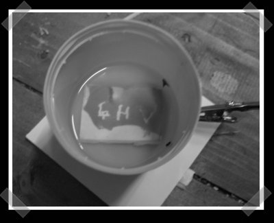
[andre] sent in his first attempt at using a HD-DVD laser diode to expose photosensitive resist to create PC boards. We’ve been meaning to give this a shot with the ol’ Epilog laser cutter. For the test, he coated the board with some resist and hand exposed it with the laser. Finally, he etched it with some sodium hydroxide.


10 thoughts on “Laser Exposing PCB Resist”
Leave a Reply to diy audio projectsCancel reply
Please be kind and respectful to help make the comments section excellent. (Comment Policy)


I suspect he *developed* the board with Sodium Hydroxide and then etched it with something else… But I can’t check ATM because the link is broken :(
Can we have a fixed link please? Cheers
http://4hv.org/e107_plugins/forum/forum_viewtopic.php?47964.0
Gio
Thanks!
I have come up with this idea too. Bungard photosensitive PCB’s are my favorite, and i use them exclusivly.
I did some calculations with a friend of mine to replace the drill in a CNC pcb miller with a variable focus bluray laser.
Long story short, it would be slow. In the range of a hour per board to expose.
modding plotter for this is stupid, just mod a Disco laser light effect (2 mirrors and stationary laser)
fo o fo
that should be “etched with ammonium persulphate” :)
I’ve not tried this with a Blu-ray LD yet, this should work slightly better but the main issue is these LD’s are a LOT more sensitive. Got the HD-DVD diode working with just an LM317T based regulator and parallel 1K resistor across the diode to take out the worst of the spikes, thanks to Sam G’s Laser FAQ for this tip :)
Additional ideas:- expose the board with UV LED’s (also works) just in front of the LD to pre-sensitise the board so that the additional radiation from the LD then burns through the resist correctly.
So far this project has cost in the region of £75 (two HD-DVD players and one blu-ray diode) so it isn’t too expensive. Plus there are lots of HD-DVD’s out there to gut and the diode(s) are comparatively easy to remove from the module as they are separate from the red LD.
Also will try the “use optical block with laser mounted underneath to alter focus in real time” trick.
I’ve wondered about whether I can read how well the diode is burning by measuring absorption of light by the dye using a green LED, this might be the next step.
Will post any improvements to the same thread on 4HV.
-A
Update:- got hold of a Blu-ray burner laser, this is rated at 100mW+
see the original link for update pictures.
Modications also include using low melt alloy to encase the metal block of the laser diode to prevent thermal runaway and hold the lenses in place, as well as using the rotary and turning mirror on an HP Laserjet printer as the scanner mechanism.
As I am using constant current drive, switching the LD is just a matter of stepping down the current by paralleling a resistor across the diode with JFET switch, this also reduces spikes to the LD and allows slow start.
regards,-A
additional modifications (probably noteworthy)
If you obtain a Blu-ray or HD-DVD module, save the top lens from the sled as in combination with a long focus lens from another DVD player sled it can focus nicely to a 0.1mm spot or better (etches incredibly fine grooves in plastic!)
Also modified a broken Sony laptop DVD writer to take the laser and optics and sense position by counting pulses from the motor’s optical rotation sensor. This is good enough that it can fine tune the PLL so that the scan speed is constant.
Added a modified ribbon cable from a broken ZIP drive as the laser power transfer cable, as it can take up to 400mA without damage (120mA is fine)
pictures to be posted soon to the 4HV thread.
regards, -Andre