Every project needs a power supply. As 3.3volt logic replaces 5volt systems, we’re reaching for the LM317 adjustable voltage regulator, rather than the classic 7805. We’ve found four different hobbyist-friendly packages for different situations.
A simple voltage divider (R1,R2) sets the LM317 output between 1.25volts and 37volts; use this handy LM317 calculator to find resistor values. The regulator does its best to maintain 1.25volts on the adjust pin (ADJ), and converts any excess voltage to heat. Not all packages are the same. Choose a part that can supply enough current for your project, but make sure the package has sufficient heat dissipation properties to burn off the difference between the input and output voltages.
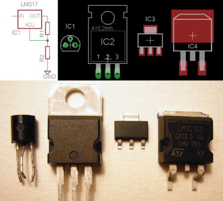
Here is a breakdown of the voltage regulators illustrated above:
IC1 LM317LZ 200mA, TO-92 ($0.59) – This is the smallest common LM317 voltage regulator. The part linked can supply 200mA, but 100mA is more common. The TO-92 package can get searing hot because it doesn’t dissipate much heat.
IC2 LM317T 1.5amps, TO-220 ($0.64) – At 1.5amps, this regulator supplies enough power for most digital circuits. We prefer the surface-mount D2Pack version (IC4) because we don’t like to drill holes. The TO-220 package dissipates a ton of heat, and the metal tab will accommodate a heat sink if you want even more cooling. Use this package if you need maximum heat dissipation.
IC3 LM317MDCYR 500mA, SOT-223 ($0.80) – This is our favorite LM317 package. 500mA is plenty of power for many projects, and the small SOT-223 package fits about anywhere.
IC4 LM317D2T 1.5amps, D2Pack ($0.83) – We design with the D2Pack regulator when a circuit uses more than 400mA of current. D2Pack is a surface-mount version of TO-220 that’s easy to solder.
Footprints for all LM317 packages are included in the default Cadsoft Eagle v-reg (voltage regulators) part library.
Want to learn more about the LM317? Instructables, [ladyada], and SparkFun Electronics have detailed LM317 power supply tutorials.


LM317 can also be used as a current limiter by tying the output pin to the adj pin through a resistor. The limited current is on the adj side of the resistor.
IO = (Vref/R1) + IADJ = 1.25V/R1
LM2937ET-3.3
Love the 317 for misc voltages however, I do dislike linear, power wasting regulators over all though.
I hope that there will be more posts on the parts series!
What’s wrong with a fixed 3.3v regulator? It saves 2 resistors.
@Tom: Nothing wrong with a fix one, for a final or working beta, but for prototyping, having a couple of spare adjustable regulators helps more.
Parts series is a good step away drom Digg2 and back towards hacks. Hoping for more.
I think switching regulator circuits have gotten easier to design and build. I tried to make a power supply from a National regulator one time, and it was a big pain. The inductor and main capacitor values depended on voltage and current, making it essentially impossible to make an adjustable supply, and it needed a lot of misc. components. Also, the inductor was huge, making a big circuit, and probably putting out a lot of EMI.
More recently, I made a switching regulator (actually a 3W LED driver circuit) from a Maxim chip, and it was a lot easier. The only components I had to figure out the values for were the current sense resistors, and all I needed to build the circuit was a FET, a diode, a couple of filter capacitors, and the sense resistors.
Right now, I’m working on a step-up converter using a MAX1771, and it looks like it will be just as easy as the step-down converter. the only issue is that I need the highest possible efficiency, so picking the components will be a little tricky.
anybody got a 3.3V regulator part#? something widely available and affordable.
thx
There’s plenty available. I have some … somewhere. But they’re sot-23.
LT1528 is a TO220 part. Depends on power , etc. .
Used one of these in a project a while back, not bad but a lot more stable if you add the recommended caps/diodes to protect it. That said it has some funny current issues, will supply a decent constant current but seems almost useless at coping with short spikes. Very useful for adjustable voltage mind you.
@matt & in general
The switchers are more involved because they require heavy loop compensation due to the LC double pole (if you want smaller inductors, design around a faster switching frequency in the regulator). However, you don’t really need to redesign your compensation for every output voltage, because it too utilizes a voltage division to set it. You’ll only affect your transient response, and it is marginal.
Moreover, switchers are best used for heavier load applications (you can find National switchers for just about any load current, but anything sub 1A is better regulated by an LDO in my opinion).
On the subject of DC-DC regulators, does anyone know of one (buy or circuit diagram) that can deliver 10v @ 2.5A from a voltage source of between 24 & 30v?
@haku
http://webench.national.com/ss1/ss?VinMin=24&VinMax=30&O1V=10&O1I=2.5&op_TA=30&O2V=&O2I=&O3V=&O3I=&onpin=I&err=I&sync=I&disty=&submit.x=36&submit.y=-1
On the note of voltage regulators, anyone know of a decent regulator that is more efficient? (a.k.a. doesn’t use heat dissipation) that makes battery packs more suitable? it there a way to effectively use a buck-boost circuit with a battery pack to squeeze more juice when the batts run below the nominal voltage?
@ pwned88 – I use these switchers myself in battery powered stuff
http://www.dimensionengineering.com/DE-SW050.htm
http://www.dimensionengineering.com/DE-SW033.htm
http://www.dimensionengineering.com/DE-SWADJ.htm
They replace the linear regulator and work well.
This was not hackaday worthy post, very off theme… bring a project instead next time.
classic 7805 can be used as an adjustable voltage regulator too, just dont connect middle pin directly to ground, I believe datasheet have right schematic for such configuration.
yes linear are power wasting regulators but if you building audio or radio you dont want additional noise
@Farles
I don’t know of a simple 3.3 volt linear regulator, something like a “7803.3”, so I use the LM317. There are several 3.3 volt (and 3.3/2.8 dual supply) LDO (low drop out) voltage regulators.
The LD1117V33 is a linear 3.3V regulator available in a friendly TO-220 package. Cheap and easy to use, just like the trusty 7805 (just add two caps).
http://octopart.com/search?q=ld1117v33
These notes I’ve made about powering circuits and the UCC283 range of LDO voltage regulators might be of interest:
http://code.rancidbacon.com/LearningHowToPowerCircuits
http://code.rancidbacon.com/LearningAboutUCC283
–Phil.
i’d like to see more of this kind of posts!!! reminds me of the good ol’ days back in tech school… keep em coming…
We’ll be happy to take requests for Monday parts posts in the comments.
Last week we looked at tactile switches:
http://hackaday.com/2008/09/15/tact-switches-for-your-next-project/
@dino – thanks for the link.
The ld1117v33 is a 3.3volt low drop out regulator. Here’s a cheap one from Mouser.com:
http://www.mouser.com/Search/ProductDetail.aspx?qs=arR7071FstdSYX%2fAthFGRA%3d%3d
@therian: actually, almost all audio consumer applications use switchers, the ubiquitious class-D amp. switchers are also widely used in radios, due to the eventual lower cost, at a significant power level. so-called audiophiles shie away from switchers, but it’s usually due to a lack of comprehension about how to properly design and filter them, rather than an inherent advantage in other types (such as class-a/ab). there are very high-class, audiophile-grade equipment which properly use class-D amps.
I’ll add zetex to the list for a low quiescent current (0.6ma) 3.3v regulator:
http://www.zetex.com/3.0/product_portfolio.asp?pno=ZSR330
several other voltages are also available.
That’s a blast from the past. I was using LM317s in kludged circuits in the mid 1970s.
Class-D digital amp(remember enthusiast trying to get sound from early apple ?, same thing just faster speed), it just so terrible idea. Power efficient – Yes, will ewer produce something better then beeeep – No
Some of the best amps, in terms of fidelity, noise, etc, are class D. You just need to have a fast enough switching speed, which is easy these days. Something like Shannon or Nyquist will prove that it’s extremely good and better then alternatives.
wow! good to start with.
There are few parameters to find out, such as: output ripple, frequency response, questient current, how to switch it off, and the price..
Is there anyone knows the circuit for the variable speed motor controller having 90VDC, 1/30HP motor. I need a controller for this motor. I already made for 24VDC motor but I need now is for 90VDC variable speed controller. Thanks.
i hav to design 24v t0 5v at 3A . when i use 7805 along with tip2955 its geting hot and i cant use a heat sink… how to do
The reason why linear regulators are less efficient, 19V * 3A = 57Watts! Try a switching regulator. The Rds on of the MOSFET means less heat dissipation. The Inductor and cap store the energy. Just be sure to pick an inductor with with a low DC resistance and a cap with a low ESR. An LM2676 would be a typical part to use.
And never use an ordinary rectifier diode in the output! Always use a power Schottky diode.
Anyone try the 7803 (3V)? There are other types of regulator in the 78xx family, like the 7812 which is 12V. I’ve had regulators in this family also occasionally output a voltage a couple tenths of a volt above the printed level when driven off of 9V. (anyone up for 3.2V?)
Hi, it’s 12 years later and we’re all gonna die! Anyway… this would have been a nicer article if the author had said more about how it works, beyond the simple formula for the resistors. To me, it’s weird you can have a 3-pin device that has pins for input voltage, output, and ground, and somehow also adjust. Of course adjust is output to gnd, but it’s weird, is there an op-amp or something in there? How does it work?
Could also mention, that with the SMD versions, it’s traditional to connect the top pin, the heatsink one, to a large area of copper on the PCB if you can, so that the copper can perform as a heatsink. Doesn’t matter if it’s also used as an electrical connection, it can still also be a heatsink.
Did this article spark off a series about other components?
See ya after the apocalypse, Ian.
Hm that laser project thing looks interesting…