Spot welders are used in the fabrication of automobiles, PC cases, power supplies, microwave ovens, electrical junction boxes, Faraday cages, and various electronics. A spot welder is used because it produces a highly defined point of contact weld. The materials are welded without excessive heating, so working pieces are handled easily. The weld is also highly controlled and repeatable. In this how-to we cover the basics of a spot welder, and then show you how to build one from a microwave oven transformer.
A spot welder’s electrodes serve at least three functions. They transfer electrical energy to the material while also holding it together; this also controls resistance. The greater the pinch force the less the resistance, which results in decreased resistive heating. A lesser pinch force results in increased resistive heating. The electrodes also conduct heat away from the material, while in the off cycles, helping to cool and temper the weld. A resistive spot weld is commonly referred to as a ‘nugget’. Spot welders are generally confined to ferrous materials which somewhat limits their application range. Most produce a weld with low voltage and high current. The welder in this How-to operates from a secondary of 3vac. The primary is 120vac line voltage that should be treated with respect. The low voltage secondary makes the welder very safe, so the electrical shock hazard from the electrode is virtually non-existent. There is however the risk of burn due to the high temperatures as with any welder.
This particular welder is not intended to weld a body panel on your 1966 Jeep; it will not work well on material heavier than 20gauge sheet metal. The intended use is for small projects, for it is not capable of continuous operation. Possible uses are as follows: Welding electrode material for electrolysis cells. Working with the fine components of a vacuum tube. Building a light weight frame for a small robotic platform. Most of us have enough parts laying around to build a spot welder. If you have a microwave oven transformer (MOT) laying around, then you are half way there. On a related note, we had covered a microwave oven arc welder in 2006.

We also needed some heavy gauge copper wire. We used about four feet of 4AWG wire to build the spot welder in the photo. Other materials included scrap 2×6, 2×2, two copper screw type lugs, two copper welding cable lugs, two MIG welder tips, two 4″ x 3/4″ zinc plated corner braces, drywall screws, and three washers.

Pictured above is a working MOT. The first thing we had to do was remove the secondary coils. Namely the high voltage winding, and the low voltage winding. We used an angle grinder with cut off wheel while being careful not to cut the primary winding.

We cut the secondary flush with the MOT laminate core. Both sides of the MOT should be cut. Inspect the MOT for signs that the laminate has been welded. We have found that welded MOTs can handle a little more abuse than their sealed only counter parts. If possible try to keep the core insulation intact, where the secondary will be wound. Though it is not a show stopper if the insulation becomes damaged. The insulation makes it a little easier to wrap the heavy gauge secondary.

After removal of the secondary we had something that resembles the above photo. If the magnetic shunt material falls out be sure to replace it as it was before. The shunt keeps the core from transferring too much power to the secondary. A magnetic ballast if you will. The shunt acts to control the saturation of the core. A brute force project like this relies on such a shunt for proper operation.

Rewinding a MOT with 4AWG is no walk in the park. If you’ve damaged the core insulators, we suggest wrapping a layer of electrical tape in their place. This will help to avoid damaging the insulation on the wire as it is pulled through the core. Our experience is that 3-4 windings is plenty. After all, this spot welder relies on high current and marginal resistance. Not high voltage.

We were careful to ensure that the secondary coil was wrapped in a helical manner to complete the secondary.

We mounted the MOT and 2×2 to the 2×6 base. This particular build used 12″ 2×6 with two 7″ 2×2. These dimensions may or may not work depending on the physical size of your MOT. The only critical part here is keeping the wire length as short as possible.

After the lower jaw was mounted, we also attached the corner braces. It was found that a spare piece of 2×2 as a shim worked well to align the upper and lower jaw. After the upper jaw was aligned we attached it to the corner braces with screws. This formed the hinged portion of the jaw.

The picture above shows the MIG welder tip and the screw type copper lug. This is an improvement from an earlier model we had built. Initially, we used copper tubing with a hole and a piece of 6AWG grounding wire serving as the welding electrode. The grounding wire was held in place by a screw that threaded inside the copper tube perpendicular to the electrode. It was very crude, but it worked. This new method is much more practical.

Here are the two electrodes ready to be fixed to the lower and upper jaws. We double checked the MIG electrodes to make sure they were tight. A loose connection will take heat away from the weld nugget.

Evenly aligning the welding electrodes, we were careful to keep the upper jaw in the natural position where it was mounted. This maintained a flat contact area for the welding electrodes. After we were sure that the electrodes had been properly aligned, the jaws were marked. We then drilled a small hole. Since we mounted with the grain of the 2×2 the holes helped to protect from splitting the 2×2.

With the electrodes mounted, we cut the wire to proper length. We never cut the exact amount we need. We always cut more than we need. This rule of thumb should apply to all electrical wiring. After all it is much easier to cut off excess than wrap a new secondary.

We bent the wires in to the approximate positions in which they were to be assembled and stripped the wire in preparation for the crimp type welding lugs. It is a good idea to strip more than is needed here as well. Simply cut off excess after sizing up the lugs depth. Never crimp insulation with the lug. This will create a potential problem area due to the loss of conduction.

Using a good non insulation crimp tool to secure the wire. We inspected the crimp and gave it the tug test. Simply tug on the wire if it is loose it will pull out. It if doesn’t pull out then an adequate crimp suitable for high current has been made.

The crimped wires were attached to the welding electrodes with screws. We were careful not to over tighten the screws. If a drywall screw had stripped out of the wood, we would have had to use a larger wood screw in its place. After both welding electrodes were fixed to the jaws, we aligned the electrodes. Using pliers we bent the electrodes so that they contacted each other evenly. The electrodes should be fairly close already since they were aligned before drilling.

We opened the jaws and wired the primary to an electrical cord and then tested the secondary. If the breaker trips, check for the following:
- The secondary is shorted (the jaws are closed)
- The magnetic shunts are missing or not properly reinstalled
- Faulty line wiring to primary or shorted primary
- Too much load on the circuit of test or undersized breaker
We observed proper electrical wiring practices. It is also stressed that this is a welder and it should have a dedicated circuit as any other welder would have.

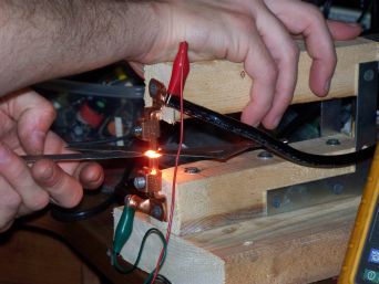
With the power physically disconnected we verified the welding electrode alignment with the material we intended to work on. Before connecting the power and performing an initial weld, we observed a few safety guidelines. This is a welder and will produce very high temperatures. Keep fingers away from the welding electrodes. Allow the material to cool prior to handling. Always wear eye protection. You may be interested in reading about spot welder parameters. There’s also the problem of combustible materials…

This Compaq used very thin aluminum to support the screen and connect the hinges. The metal broke and destroyed most of the lower plastic. We were able to make new supports from 22AWG stainless steel sheet metal. All the welds were made using the spot welder with a special power controller. The power controller will be covered in another how-to.
[youtube=http://www.youtube.com/watch?v=VG1xVNpm7k8]


This project is nothing without the power controller circuitry.
Hackaday, you had better make a followup post! =D
I totally agree with Jeeves !
So now and then I visit this site to see if this followup has arrived,
for months now , and . . .
NOTHING !
Not bad, but I would be interested in a bit more umph. Something that could do automotive grade sheet metal. Any suggestions there?
wire more in parallel
@jeeves: Power controller circuitry? I don’t believe it has any. Just the primary to mains AC via a circuit breaker.
thw guy should have crimped his connectors the other way around, he loses a tiny bit of voltage like this!
great tut. can’t wait for the next part!!
spot welders and welders in general are easy demos of basic electrical physics, and therefore easy for many of us to make :)
@tecnik
I refer you to the last two lines of this article:
“All the welds were made using the spot welder with a special power controller. The power controller will be covered in another how-to.”
http://www.harborfreight.com/cpi/ctaf/displayitem.taf?Itemnumber=45689
@spotty: So what? I can buy my radio gear, or I can learn the ins and outs of what makes it work and build it myself. Try making something for yourself instead of buying it.
omg I MUST MAKE ONE
I’ve made one like this, and they really are just that simple, if a bit underpowered. This really doesn’t need much in the way of control electronics, though a timed weld cycle apparently helps with making a consistent weld. Mine just had a light switch, which I flipped while counting ‘one one thousand’. I’ve seen others that used a timer relay. A lot of spot welders have something to control the pressure. That has a big effect on weld quality and consistency as well. One way to easily rig something like that up is to hang weights off of the upper arm. Put a spring under the arm to raise it a bit, and hang the weights from a long cord so they’re near the floor. Put a ‘see-saw’ pedal arrangement under them so you can step down to lift them up, and release to trap your workpiece in position.
in other news, I like the use of the MIG welder nozzles as tips here. Next time I replace mine, I think that’ll be a good shortcut compared to filing tips out of copper rod.
K.
that will be my next project. just gotta wait for big garbage day.
fun fun with this artical most hacker shops should be damb near the point of having close to a real “replacator” from star trec…lol
Little primitive welder doesn’t need controller.
Damn, now I want a helical manor (sounds so suite!)
Cool, time to spot weld some sheet metal.
@teck monkey:
English is not your first language, is it?
Very fun. I have several welders, but I really want to build one of these, just for the little things I need to tack together. I used to use a smaller spot welder for doing strain gauges, it had a hand held unit for welding and a triggering switch in the hand unit. Now I know what parts to “find” to build it.
I’ve actually built a spot welder (capacitive discharge) for shim stock, mainly for making battery packs and building things at work. It uses a 1.5 Farad stiffening capacitor (ordered off Amazon), a SCR, and a foot switch with a few copper probes attached. Works pretty well, actually.
Simple home shop ( check out the Lejay Manual) constructed spot welders are nothing new. I believe operator experience and skill are the only power controller circuitry really needed. That thought posted being mindful of the author’s note on power controller circuitry. I’m not saying such circuity wouldn’t have it’s place
Alchemyguy, relax dude, I doubt the harbor freight link was nothing more than a FYI for anyone interested. Respect fully, simply building an oscillator or an amplifier from instructions, can teach one the underlying principals why they work. For example in the project the Author tells you to be mindful of how the transformer secondary is wound, but that in itself doesn’t teach anyone why it’s important to be mindful. OK, time to take my own advice to relax, and move on
digidev; your eyes are better than mine as I cant tell if those connectors have a spit barrel where the is correct way to crimp them. Any way this tool depends on current not the voltage at the tips. Though voltage plays a role in how easy it is to strike and maintain an arc while arc welding
just say “squirming coil”…..or alternator…..it’s what creates the electrical charge.
I want your scope.
got any adobe software or early century california pottery, or best of all a heat press?
or $80 cash and a favor, and with that comes a recreation of ANYTHING you want done in photoshop/printing.
@the controller.
it adds the ability to fine tune the power of the weld. it is best used on small jobs like welding the materials inside of a tube. A bump switch would probably work if the extent of the control was simply power. But i have some other plans for the controller which include using a load cell to properly profile various welds. A very rough version of the controller can be found by looking at my older videos
Just so i don’t get stuck adding features, i’ll end it at that
A microwave can’t act as a cylioscope?
Scientific American had an article in their defunct Amateur Scientist column that showed how to make one incorporating a rat trap
hmm… philpem did one on hackaday a while back using 600,000 uF worth of capacitors and a special SCR to switch the current. I did experiment with using a 1F audio capacitor but the words “overkill” come to mind, needs some control on the power even at 10V.
what would be useful is a “tailbiter” circuit that discharges the capacitor into a resistive load some millseconds after the start of the main current pulse, providing more controllable results.
-A
Could this be adapted to weld tabs to batteries (for making/repairing rechargeable battery packs)? I saw a how-to a few years back that used big-@ss capacitors but could never find any (affordably) to use in constructing one.
Someone should mirror that geocities link on rewinding MOTs before it dies.
Wood is a bad idea for this project, or any involving high voltage/current electricity. Albeit poorly, wood DOES conduct electricity and the welder risks shock and/or fire.
This looks terrific. I do have a few very basic questions:
1. I’m a bit unclear on the following excerpt:
> The first thing we had to do was remove the
> secondary coils. Namely the high voltage
> winding, and the low voltage winding.
In particular, I’m unclear how the windings differ from the coils here; I took them to be synonymous in general. Doesn’t the mot step up voltage from mains to the kV range, and so isn’t the secondary the high voltage side? The final bit is what’s giving me troubles.
2. Also:
> We cut the secondary flush with the MOT
> laminate core. Both sides of the MOT should
> be cut.
Aren’t you just removing the coil on one side of the mot? What does “both sides” mean here?
3. What in the image is the magnetic shunt material that we need to avoid losing? Is it that beige material around the core inside the primary?
4. > We observed proper electrical wiring practices.
Could you elaborate on this? I’m clear on standard practices but I’d like to make sure on the details in this case?
5. Safety question: Does a spot welder have radiative emissions that are dangerous to the eyes? In other words, is some sort of UV/IR protection necessary? You say safety glasses, but I wanted to double check that something like welding goggles weren’t necessary.
6. Another safety question: If getting the mot out of an old microwave, what precautions should be taken concerning the possible Beryllium oxide on the magnetron? For example, on the chance that the oven was tossed around after being discarded, breaking the ceramic insulator. Is doing the job outside with a P100 respirator sufficient, insufficient, or overkill?
Thanks!
static,
I must thank you for mentioning the Lejay Manual, it’s a revalation for me. Years of hearing about my grandfathers adventures with things electical and knowing that he didn’t have the background to come up any of it. there it all is with step by step instuctions. So my grandfather was just like me, he read too much. what he could have done with the internet!
@chris
1) Microwave oven transformers actually have three windings. The first, is the primary. This is what takes juice from the wall and energizes the core. The next is the high-voltage secondary. The produces a couple of thousand volts for the plate in the magnetron. The third winding, consisting of no more than three or four turns of wire, is the low-voltage secondary, and is used to light the filament in the magnetron. The instructions could probably be worded more clearly, like, “remove all the windings except the primary.”
2) This just reflects the author’s technique for getting rid of the windings in the secondary. If you cut away the exposed windings on both sides of the core, all that’s left to do is to use a piece of dowel to punch out the wire strands still stacked in the core. BTW, I have found that a sharp wood chisel and a mallet does a fine job of cutting away unwanted windings, and produces less debris than a hacksaw.
3) The magnetic shunts are little pieces of metal wedged into the the opening in the core. Most times, when you are hacking an MOT for a power supply application, you want to remove these, because they degrade regulation. In this application, I think I’d agree that they need to remain in place.
4) Do what you can do to eliminate electrocution hazards. All the connections on the 120 VAC side should be well insulated. Power should be supplied with a heavy 3-wire cord, and the core of the transformer grounded. Also, since the primary windings are largely exposed, the entire transformer should probably be enclosed in a box with grills and a cooling fan. A would also fuse the primary side.
5) I would be concerned about UV. I wouldn’t use a piece of equipment like this without eye protection.
6) I’m not certain that beryllium is used in these tubes any longer. Even if it is, the entire oven would just about have to be crushed flat in order to damage the tube. I think a greater hazard is the possibility of a charge remaining on the high-voltage capacitor.
@sparky
That clears it up for me. Thanks for the very helpful information!
how would i tap weld ni-cad or nimh cell?
the bottom probe touch the – of my battery and the top probe touch the + and the metal i am trying to “solder”?
so the energy goes right through my battery?
i am interested to tab weld a123 nano phoshate battery.
i got my answer just by googling it :)
http://www.rcuniverse.com/forum/m_8265553/tm.htm
he use 1farad cap from car stereo :)
you put the prob next to each other!
now i can’t wait to see how he made the “special” controller!
thanks
The secondary wire could be formed into a loose coil first, then “screwed” onto the transformer as an easy way of winding it. Or maybe making a bundle out of thinner wire for flexibility, then insulating it with shrink tube.
Once the welder is complete, you could make a second set of electrodes, and weld them together for better performance. Would filling in the gaps with solder be a good idea?
When you got enough power to melt steel solder’s just a boiling hazard.
how would i tap weld ni-cad or nimh cell?
the bottom probe touch the – of my battery and the top probe touch the + and the metal i am trying to “solder”?
so the energy goes right through my battery?
….boom…
you want to have 2 electrodes close together on the same side(like… ========) you would touch the dual(or quad?) electrode to the thin metal bus which is pressed into the top of the battery, at the 2 thin points of contact it would weld
@ tinyhands; Wood is just fine, safe for this project. In most home shops, the duty cycle is most likely going to be low enough, the risk of fire is not existent. Unless one pulls a stunt like the person in the USN and penetrates their skin with the secondary leads in a manner that allows the current to cross their heart, the secondary voltage here is safe. Millions of electri arc welders whould have never been constructed if there was an electrocution hazard.
Frankly with 2 arc welders in the shop, I’d use 1 of them for the power supply. Other wise I’d try a car battery first. With no arc to strike and maintain 12 V. may be high enough, more than enough current. For welding solder tabs to battery cells. This MOV mod combined with the other persons electrode holder, would be the ticket.
Hi, I want to build a spot welder but am not sure how to build it for what I need it for. I want to spot weld 16 gauge wires to make bird cages. Would like to have a jig setup so I can place the wires 1/2″ apart with 4 cross bars here is a picture of it. http://www.kentcages.com/ShowCageNorwichCanary.htm
Any help would be great.
I love this project both for the simplicity and for the fact that it makes NO MENTION of the Bus Pirate! Seriously though, It made me want to build one even though I have no immediate use for a spot welder. Someday this link will be like gold…
I’m making one of these and enclosed the transformer in a box i made from the microwave’s sheetmetal. Will enclosing the transformer in a steel box affect the magnetic field either strengthening or weakening it?
Hi I need a spot welder to make model ships I have Done the thing as far as I can but useing 240v i got 1.5v out of the end of the 4 gage wire I don’t know what amperage I am gettig as I don’t have the equipment to read it but so far it does not work? Could this be bad connection( and I will mke another set of jaws)?or does the low voltage have this effect?
Nicely done! Your use of existing welding parts mixed with existing electrical parts show quite alot of innovation. I once use a spectacular engraver using very low voltage and high current. It had a copper pointed hand tool and could produce beautiful script on the most hardend tools. It was very controlable. Much better than any mechanical engraver.
Respected Sir,
I am searching for home made spot welding circuit and hand held welding fixture for small and precision spot welding of 0.5mm & 3mm length of metal wire on 0.5mm thickness of metallic sheet. Kindly help me by giving technical in-formations to enable me for self assemble.
Thanking you.
i love it from China
Evening.
I have a 120v-24v transformer rated at 10A. It has dual primaries. I assume this is for adaptation to a 220V line voltage. I was originally going to use this to make an induction heater, but I was wondering if this could be used for one of these spot welders instead? I agree that the voltage and current are a little off, but I am using it for joining steel wire rings to make solid chain links. The largest grade wire I’ll be using is 16 or 14. Is this enough or would I do better just to find an MOT?
Thanks for your help.
Very good IDEA!
Low cost & simple .
I will tray it !
Grate for servo brackets
Hi, Im a brazilian student of electrical engineering, and sorry for my bad english.
Im trying to make a welder like this, I follow all steps, my the primary circuit has no resistence and close-circuit and my ‘disjuntor’ opened here. What you think? Maybe when I cut the secondary, some swarf ‘iron filings’ into the primary.
Can you helo me?
Could you build two of these transformers hooking up the primarys in parallel and running the secondary winding in series to create enough current to spot weld body panels?
What I don’t understand in this circuit, is that the new winding is used as secondary.
As it has less windings than the primary, wouldn’t this step the voltage *up*? Or does it step down because the wire thickness gives more inductance?
And, what voltage output does this give?
–Nathan
If primary has more turns than secondary, and you put voltage in primary, then it steps voltage down, by the ratio of turns, and it steps up available current by the same ratio.
Thanks for the explanation :)
I understand most of it but I have a couple questions about wiring.
1) How can one tell by looking at the mot, which is primary and which is secondary? Will secondary have more turns with a smaller wire gauge?
2) Wiring to a home outlet: As simple as soldering a spare extension cord to the positive and ground wires of the primary coil? Or is it more advanced?
Also, what size breaker are we looking at? Could I, perchance, hook this thing up in my garage to a standard 120v outlet after unplugging my drill battery charger, or is it more advanced?