
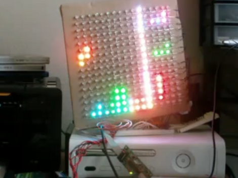
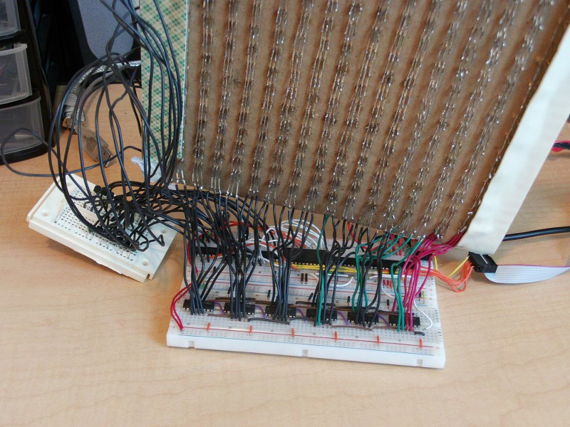
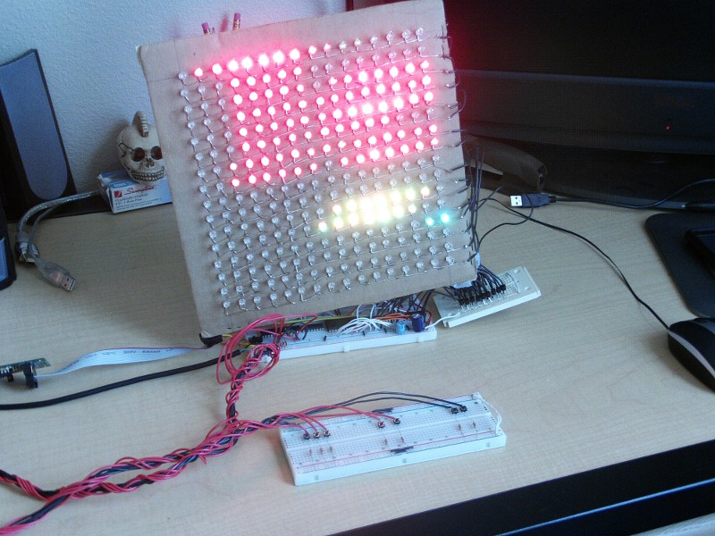
[Stan] built this LED matrix using a 16×16 grid of RGB LEDs. He built the hardware and wrote some subroutines to randomize the colors. He’s not using PWM because frame buffering is not feasible for the 1k SRAM limit of the ATmega168 he used. Instead, shift registers drive the lights which can be mixed to achieve eight different colors (including off for black) reducing the framebuffer size to just 96 bytes. After he got done with the build he realized this is sized well for a game of Tetris. We’ve seen AVR tetris, PIC Tetris, and Tetris using composite video but it’s always a pleasure to see a new display build.
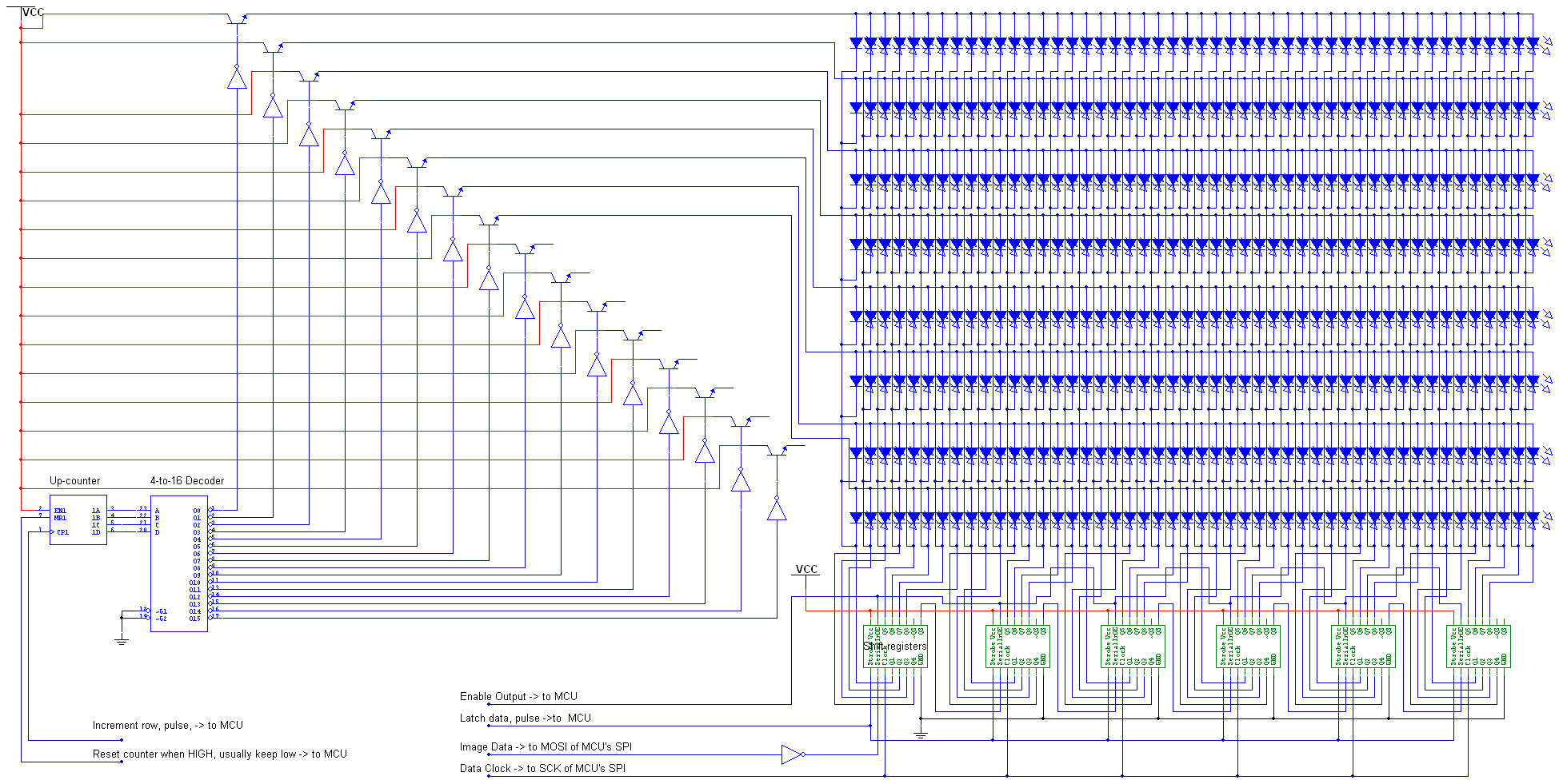
After the break we’ve embedded [Stan’s] demo video, several pictures, and a schematic. He’s using many of the same principles outlined in our How to Design an LED matrix tutorial.
[youtube=http://www.youtube.com/watch?v=ugub6d65b2A]


Why would PWM not be feasible? I understand you don’t want to do 24bit color with it, but surely 8bit (3r 3g 2b) should be doable? It’d take 3/4 of the sram, but in the worst case you could put the game logic in a 2nd AVR.
good, but would’ve been even better if board was painted black
I imagine if he’s using shift registers for both axises, that’s another reason why you can’t do PWM. You just can’t shift out fast enough.
Simply beautiful!
@Bill that’s not the case, from the same 3 io pins (h-clock, v-clock and data) you could easily do the eight passes (per line) that a 3 bit/colour needs stalling the other clock or do eight “frames” per frame (as they do for monochrome flipper dot-matrix displays), since it’s small enought the math can be this: data-frequency = 16{lines}*16{cols}*3{colors}*8{shades per color}*25{fps} = 154kHz
not so intensive for a 16MHz clock (3 ops of 1000)
You are thinking to much like a video signal.
He’s running 14.7Mhz, refreshing the screen at 60 Hz, and he has three data lines, a h clock line, and a v clock line; 5 IO pins. Realistically, he’s maybe shifting out at max 1.8 Mhz assuming it takes at least 8 instruction cycles to set 3 IO pins according to a bitmap, and flip a clock pin. So now the fastest you can shift out a row is at 114 kHz. This doesn’t even count the cycles between rows and the other time needed to generate the bit map from the code.
Not to mention, he’s already at a 1/16th duty cycle from the scanning already. Even if you manage to shift out to each row three times, you’re talking about obtainable duty cycle levels at 1/16th, 1/24th and 1/48th duty cycle. LEDs fall off brightness very rapidly after 1/16th as it is.
I have a similar LED matrix ‘driver’ board that I am designing:
http://www.billporter.info/arduquee-an-arduino-powered-marquee-design-log/
I tried several ways to attempt PWM through x and y shift registers, none really worked. Either the duty cycle fell off too quickly, or the frequency would fall out of human POV range.
Well originally I found really nice 12-bit per channel pwm drivers which I was using, that’d make it into 48-bit color image. It was displaying the image well, however 48-bit 16*16 image would take a bit more then a kilobyte, and the microporcessor I had has only 1024 bytes SRAM. So after that I decided to use shift-registers just because of simplicity.
Once I get time, and some money for components, I do plan to turn this screen in 24-bit or maybe even the original 48-bit color screen :)
1. Spawn systems is probably the worst I seen.
This is the coolest thing I’ve ever seen! Stan did a great job!