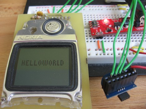
At the beginning of the Month we came across a coupon code for a free eZ430-F2013 development stick. TI has given these things now and again so we took the opportunity to acquire one. It arrived yesterday and we’ve spent just a bit of time looking it over. Above you can see the first project completed; Hello World on a salvaged Nokia cell phone screen. Join us after the break for our thoughts on the device, as well as more pictures and details.

The development board comes as a USB dongle. But this isn’t the extent of the packaging. It came in a DVD case, along with a CD that has User’s Guides and “web resources” on it. We don’t need this, but okay. But wait, that’s not how it shipped. The DVD case came inside of a 9″x9″x10.5″ box that was shipped priority overnight via FedEx. That seems a bit wasteful, especially considering that we didn’t pay a dime for the hardware or the delivery. A manila envelope would have sufficed, but if it’s free we don’t get to make the decisions about this stuff.

Inside you’ll find the mainboard with a USB connector that makes up the programmer itself. The hind-end is small detachable board that hosts the F2013 microcontroller. The case was a bit finicky to remove but a little bit of prying does the trick.
0451:f430 Texas Instruments, Inc. MSP-FET430UIF JTAG Tool
When plugged in an LED on the daughter board happily blinks away as the example firmware intended. We were pleased to see that dongle was recognized by Ubuntu 10.04 as a UIF device that MSPdebug, the software we used to program with the Launchpad, can talk to. Time to make this little guy do something.

Here’s the microcontroller board. Note the small-pitch 4-pin socket for connecting to the programmer board. Also note the unpopulated 0.1″ pitch pads.

Here’s the underside of that board after adding two 7×1 pin sockets. This is where we discovered a nice design consideration. Since we didn’t have any IDC sockets that are this large (to plug into a pin header on is board) we went with the pin socket and will just insert jumper wires. Now that they’re installed we realized that the pin-out from the bottom is the same as the chip would be from the top; pin 1 in the upper left and pin 14 in the upper right. Time to hook this up to something and start coding.

We pulled out an old Nokia 3595 LCD screen that we’ve used in the past because it uses 3.3V which is the upper end for this chip. Porting the code over was a snap since it was already used with another MSP430 chip. A few minutes later out pops ‘Hello World’. To review: it was free, works with Linux tools, and it seems like the code works across several different chips. Win!
Our Thoughts on the Hardware
So what do we think about this as a development package? If it’s free, great! We’re a little baffled because it seems to be disposable hardware. No thought has gone into using the programmer for anything other than TI’s daughter boards that have the fine pitch connector. We’ll most likely end up gluing a pin header to the plastic case and soldering those pins to the proper connections to make this more robust. We do get the feeling that one hand doesn’t know what the other’s doing over there because the Launchpad feels like superior hardware. That being said, neither of the development boards have made it easy to program and debug off-board so for now we consider both of these as novelties.
You do have to give them credit though, by giving it away for free we now have an MSP430 chip already on hand for the next time we’re prototyping a small project. And this might be just the thing to use the 1.8V serial EEPROM we ordered a few years back thinking we were getting the 5V version.
Resources
It’s nothing special, and probably of no use to anyone, but here’s the git repository for the hello world code.


TI appears to be dong a fire sale on all it’s toys lately.
I just received my Stellaris robot development kit last week. I mean, who could pass it up? You guys posted the coupon code here and to get a $150 platform for $25, you just can’t say no.
The only thing about TI is that their fulfillment takes a LONG time. It was a total surprise when I got the shipment email for the Stellaris.
I got them when they were free too and I having a hard time to think of a use for them. I think thats the real reason why they were just giving it away. I suppose they’d be good if you wanted an mcu for a project and wanted it to be small as possible, and didn’t have the means to make boards that small.
Currently making a binary watch…
The external crystal interface with selectable capacitance is making it so easy!
Great little uC’s
“That being said, neither of the development boards have made it easy to program and debug off-board so for now we consider both of these as novelties.”
Either the EZ430 or the LaunchPad can be used to do in-system-programming. All it takes is 3-4 wires from the programmer to the system. Granted, the fine-pitch header on the EZ430 doesn’t lend itself well to this, but the header on the LaunchPad is easily connected for ISP.
Also, see http://www.43oh.com/2010/12/turn-the-ez430-tool-to-an-ezprobe/ for a really cool use of the EZ430!
BTW: One trick to make the EZ430 easier to use for ISP is to sacrifice a target board by removing the MSP430 chip and installing a header as you did in the article. (Extra target boards are 3 for $10.)
And you did not tell us about the give away why?
Edward: They did. Thats how many of us got them for cheap/free.
I’ve always shied away from the MSP-430 due to the lack of cheap compilers that allow use of the entire program memory range.
I last tried using their EZ-RF kit, but their RF library filled so much of the allocated space I had issues getting any of my own code to fit!
Where ?
I’d like to see a feature thing with coupons like this or a topic in forum . That would be awesome !
@GeekDoc: I disagree about the Launchpad’s header. There is no ground connector on the 2×5 header that connects the top and bottom portions of those boards. So yes, you can make connections via the breakout headers, but it would have been a good design consideration to include a programming header that you can plug in an IDC connector to. I think there was room for it on the board, and if left unpopulated it shouldn’t raise the cost of PCB production (unless they’re charged for extra vias).
Nice idea on putting the headers on the bottom….I got the same deal, but I put mine on the top, so everything feels backwards.
All of mine arrived via the MSP430 day events that the company threw. Now that event is merged with their regular TI Tech Day events. But I am more interested in how all of you salvaged that Nokia 3595 display from the attached phone unit.
The MSP430x20x1 on there is good from 1.8V to 3.6V and the EZ430-F2013 supplies it with 3.6V according the TI user manual for it.
The newer EZ430-F2013 sticks like in the photos have 6 pins for the dev board connection J1 instead of just 4. The actual dev board itself still only uses 4 pins but the 2 extra pins are for a UART. Pin 1 = TX and Pin 6 = RX.
http://focus.ti.com/lit/ug/slau176d/slau176d.pdf is the user manual.
Is it possible that row of five doughnuts on the side of the mainboard carries the programming signals as well?
@Mike Szczys:
A fair point. It would have been nice to have a ground pin in that header (J5). Then they could have separated the ground planes, as well.
For in-system programming, I just use one of the pins in the corner opposite the USB connector (J6). I just have to separate the cable a bit at the LaunchPad end (single ground connector to J6). Granted, not as convenient as the extra ground pin on J5 would be, but works fine.
@MRE – The row of test points along the bottom edge is the JTAG interface to program the MSP430F16x on the bottom.
Hey guys –
I’m one of dozens of new college grads who Texas Instruments has been hiring to be a refresh to their (soon-to-retire for the most part) Applications Engineering team. I have been part of the “hacking” community for a very long time, and now I have a chance to get OUR (yours and mine) feedback to the places where it counts – I have direct links to the guys who design our EVMs, and I want to open myself up to receiving feedback from groups like these.
I can’t guarantee that I’ll be able to respond to each of you (this is a personal endeavor), but I’ll do my best to get your feedback to the right place.
texasInstrumentsDude@gmail.com
Bummer.. guess theres some aftermarket opportunities for cables with tiny connectors then ;)
I got my eZ420 in 2006 and I’ve never used it for anything.
@JP
Why not have them make these EVM units more Linux friendly, and proper support for Windows Seven?
@GCL
From my experience so far, TI has concentrated on satisfying the needs of their largest market segments first – most of which are companies that use Windows. Many of my colleagues and I would like to see expanded support for the open-source MSP community, and I will be emailing the team in charge of this effort to see what is being done or planned to enhance TI’s open-source presence.
The latest version of Code Composer Studio is listed as compatible with Windows 7 [I’m curious what specific issues you are havinig]. According to IARs website (http://supp.iar.com/Support/?note=64346&from=note+62867), it seems that Windows 7 support is still a little finicky.
Obviously, full Windows 7 support will be required for Texas Instruments to continue to support it’s customers, so keep an eye on the tools for updates that address those issues.
Again, I’ll be asking the appropriate persons for more complete info about this stuff. I’m also hoping to get an article on here specifically to get feedback like this.
JP
I really wanted to get one, but unfortunately I was too late and the coupon expired :(
@jp open a thread in the forum if you want easy to find place to get feedback
Hi, I know which the post is old,but I’m beginner and I would like some tip of the how to put the Msp430F2013 for work out the kit(Stand alone), I want to use other pins for test, I placed one battery on the pins 1 and 14(vcc and vss), but nothing hapenaned(was for to blink the led).Thanks!