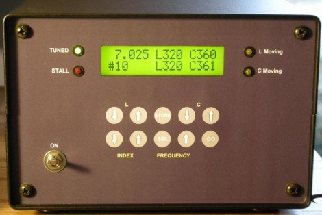
A few years back, [Floyd, K8AC] built a high frequency autotuner as an addition to his Ham radio setup. Based off a design he saw in QST magazine back in the early ’90s, he has been using the tuner almost daily for the last few years, on both the 3.5 MHz and 7 MHz bands.
Built into the wall in his radio room, it is a pretty impressive sight. His “L” circuit is controlled by a pair of mechanically coupled inductors which are driven in concert by a pair of two-way motors. The positioning of the C and L components are monitored by a PIC controller which stores the tuning data for up to 30 predefined frequencies. A couple of button presses on his controller’s front end sends the tuner into action, dialing in his unit’s inductors and capacitor to their proper settings. The PIC monitors the tuner’s progress, informing him when the proper frequency has been tuned in, or if the frequency can not be set, indicating issues with the equipment.
His setup has undergone several revisions over the years, with the most recent iteration being the most automated of the bunch. Check out his site for plenty more details, or keep an ear out for [K8AC] on 40 or 80 meters.
[Thanks, Rich V]


This will not make you sound like mega-gigabyte T pain
lol, Garreth you made my day
@Floyd,
Cool setup, especially the mechanical part :)
Have a question/suggestion though. Wouldn’t it be fairly straight forward to replace the manual entry of the working frequency with a simple freq meter that will let MCU know what the current point should be?
Also, I’ve seen fairly significant environmental (mostly weather related) impact on the antenna system’s impedance, so having static/predefined values for LC filters components usually does not get you the best SWR possible.
There are fairly straight forward and fast converging algorithms for tuning 3 parameter systems (your LCL for example), especially fast when you have a good starting point (the predefined values you already use).
Might be worth considering in your next release :)
@Miroslav-
I’d be interested in seeing a description of those algorithms. Do you know of any documentation on the web that discusses them?
@Pookey
Don’t have anything specific to offer now, but here are some ideas to consider:
1) system has 3 “orthogonal” variables (meaning that you can not tune one independently from other two)
2) there might be multiple “sweet spots” (combination of LC values that are better then nearby values)
3) in most cases there is no need to find the “sweetest spot” (as in an absolute minimum SWR). The algorithm should have an “acceptable” value for achieved SWR, and once you find th local minimum with SWR better then stated, tuning stops. (As on “stop trying if you find 1:1.3 or better”)
4) Having predefined start values for particular frequencies might speed up convergence (that’s what described system has today)
So, the system with three orthogonal variables is actually very complex, but accepting assumptions above can be simplified to something that simply said will achieve acceptable, but not the best, results.
a) get the frequency
b) look up and set to predefine start values
c) measure SWR
d) change one value, measure SWR, if better continue, if worst, change “direction” of the change. When you find local minimum, do the same with the next component. If desired, repeat the process around that new combination of values
Finding the absolute minimum is much more complex and would take a long time to achieve (converge). As values are orthogonal, finding the sweet spot (minimum) for each one does not mean you will achieve an absolute sweet spot.
Just another idea out of the left field. Not even sure if technically/theoretically possible.
Measure the complex impedance of he antenna system for given frequency, calculate the LC network for given output impedance of the transmitter, do some math, adjust values.
There are some “small” obstacles with this approach, one being that transmitter’s impedance is not a constant value, the other being that antenna system’s impedance might change with inserted power (especially if you measure with mW and then use with kW), not to even mention that measuring the complex impedance is not quite straight forward.
Just an idea :)