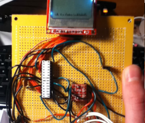
[Fred] dropped a note in our tip line to let us know about arduino forum user [bilbo]’s latest project: A 3-in-one spectrum analyzer, oscilloscope, volt-meter combo. The build consists of an Arduino, radio board and Nokia 5110 LCD breakout board. The (thin) video after the jump shows the rig in action. Though soldered to a full sized perf-board we can see later, smaller, battery powered versions prove useful in rooting out wayward bluetooth signals, or just finding that lost microwave oven. Although [bilbo] uses the same radio board as similar builds his creation boasts several different display modes, as well as doubling as a volt meter and miniature-oscilloscope. There is no shortage of previous spectrum analyzer builds, but this one is the first one we have seen running on an Arduino.
Thanks for the tip [Fred]! If you feel like wedging some frequency scanning capabilities into your next project don’t forget to check out [bilbo]’s forum posts for source code!
[youtube=http://www.youtube.com/watch?v=fKIXmWpsmYs&w=470]


Along a similar-ish line from last year:
http://hackaday.com/2010/12/29/bringing-the-shark-to-the-bee/
I am not an expert. I also have not read TFA. That said, calling it a 2.4Ghz spectrum analyzer is a bit misleading. Not, that it isn’t a really (really) hard problem to solve!
Chances are it’s analyzing baseband at some 10s of Mhz. The arduino doesn’t have the chops for the full 4.8Ghz sample rate.
@fdawg4l
Indeed, you haven’t RTFA.
This article and the original mention the use of a radio module.
Namely a CYWM6935 WiFi module, whose RSSI output appears to be used to do the acquisition.
@Johnathan,
I gathered that from the code snippet he posted. Again, I’m not an expert, but I believe my theory about it not being 2.4ghz spec an. stands.
RSSI means it’s actually demodulating and decoding a signal. A spectrum analyzer will show you the spectrum regardless of the presence of a signal.
Has anyone else noticed the nice label on the MCU, really simple, i must implement that on my teaching units. such a great idea.
Can anyone explain to me how that is possible? I donno the arduino’s clock speed, since my thing are PIC’s, but according to Nyquist theorem, to acquire a signal, for fidelity purpouses, one need to sample it atleast 2 times faster than its frequency. How can it be done at that speed with a microcontroller (and it also handles graphic display oO )… Sorry for bad grammar, english is not my first language
Yeah, I second labels on the micro.
Makes sense and avoids expensive mistakes when swapping chips over.
What would be pretty clever is to have the programming and USB pins on the chip broken out via an optical interface like the TOSlink so that it is fully isolated from the host PC to reduce noise.
Hey all, i’m the one who made this project. Just to address a few things:
-I can’t claim complete credit for the chip label idea. Sparkfun does it on the atmegas that they sell, and it seemed like a good idea so i made one for mine.
-About the frequency issue, the radio module scans in channel widths of 1 mhz, and the total power of that band is displayed, even if there is not another device transmitting on that frequency.