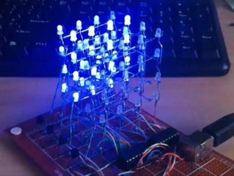

[Kirill] wrote in to share his ATtiny hack, a 4x4x LED cube. The 64 LED display is a great choice to fully utilize the hardware he chose. It’s multiplexed by level. Each of the four levels are wired with common cathodes, switched by a 2N3904 transistor. The anodes are driven by two 595 shift registers, providing a total of 16 addressable pins which matches the 4×4 grid perfectly. All said and done it only takes seven of the ATtiny2313’s pins to drive the display. This is one pin more than the chip’s smaller cousins like the ATtiny85 can provide. But, this chip does include a UART which means the project could potentially be modified to receive animation instructions from a computer or other device.
You may have noticed the USB port in the image above. This is serving as a source for regulated power in lieu of having its own voltage regulation hardware and is not used for data at all. Check out the animations that [Kirill] uses on the display by watching the video after the break. You’ll find a link to the source code there as well.
[youtube=http://www.youtube.com/watch?v=d4na-kO2q1Q&w=470]
Here’s a link to [Kirill’s] source code: http://www.mediafire.com/?c47p92t0rl3z90p


Inb4 not a hack! I really like the way this is put together; quite simply. I’d love to know how the animations are written; whether theyre hard coded, or calculated on the fly.
…Not that I’m an electronics master, but why not use a single sixteen bit shift register/LED driver like the TLC5928?
Likely wanted to stick to through-hole parts, since it’s on veroboard. Plus, the 595s are ubiquitous, even to the novice.
Alas, that makes me less than a novice! ;)
Good point on the SMD/TH call. It’s a real bitch trying to prototype with these unless you have extra parts.
Not really a hack to be honest. The 595s do all the work. You can drive the cube with an 8 pin tiny45 as well.
Hey there — someone mind clearing up some of my confusion with a number of LED matrix/cube projects? It always seems like folks are running their shift registers way over the max ratings (when all LEDs are lit), or I’m just way off on my calculations…please be gentle on your response ;)
I’m looking at the 74LS595 datasheet and seeing I_CCH for the 595 to be 50 mA, and I_CCL to be 65 mA. With those 68 Ohm resistors and V_CC = 5.0V, we’d be sourcing roughly 70 mA for each LED connected to that shift register.
I must be wrong…otherwise if all 8 LEDs connected to the 595 are on…those shift registers would be getting mighty hot, right? ;)
I see the 596 has open collector outputs, which might certainly alleviate this issue a bit, if there is one…
These are 3.2V led, thus the current is about 25mA.
duty cycle of 50% = 1/2*power so if it was 70ma and it is on 50% of the time the shift reg. will heat as if a 70ma/2= 35ma..: <50ma
i didnt look at the sourcecode but im assuming the code is loading while the LEDs are off and then a delay while they are on, i was assuming the program took 50% of the time and the delay would be the other half.
Transistors:
Each of the four levels are wired with common cathodes, switched by a 2N3904 transistor.
Sure…those transistors are sinking that current, but I’m still confused how the 595’s can source the 5V / (68 Ohm + some additional series resistance) A. I guess the low duty cycle clears it up for me though…
The ATtinys can do i2c…I think this could have been done using an ATtiny25/45/85 and a MCP23018.
You could just use 3 shift registers instead and would be able to run this on a 4-pin uC, I believe.
how easy would it be to convert to sensors/input for a directional sound indicator?
…or you use two more pins and need no shift register whatsoever:
http://tomscircuits.blogspot.com/2011/07/charlie-cube-mark-ii-4x4x4.html
Can we please make this the last LED cube projects for a while? It seems like that kid from NZ threw down the gauntlet for everyone for a while…
http://www.instructables.com/id/Led-Cube-8x8x8/
/no offense meant to the builder
//enjoying the ATiny coverage over Arduino tho :)
Yet another LED project with no transistors on source side.
Nice circuit :) I’ve planned to build it but some problems occured during compiling the source code…could you send me The hex file? I’d be pleasant.
my address: szabi155@vipmail.hu
Great site anyway :)
THANK YOU!!!!!!!!!!!!!!!!!!!!!!