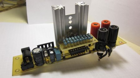
 Inspired by a design he saw on the EEVblog, [George Graves] put together this constant current dummy load. You might need on of these if you’re testing power supplies or batteries. They pull a constant current regardless of the voltage of the supply. [George’s] version extends the range of the original a little bit by running the op-amp at 8 volts. He says that everything runs fine at 1 amp. He tried 2 amps but things got hot pretty quickly. What we really like though, is he took fantastic pictures. Sometimes even simple things can catch our attention with the right pictures!
13 thoughts on “Constant Current Dummy Load”
Leave a Reply
Please be kind and respectful to help make the comments section excellent. (Comment Policy)


wonder if this could help: http://www.elektor.com/magazines/2012/may/lossless-load.2135766.lynkx
That’s not nearly the same thing as shown here. It’s not meant to continuously sink current.
I built this circuit too, it was a nice fun weekend project, and I don’t know how I haven’t had one on my bench all this time.
For the sense resistor I used 40 half-watt 10 ohm resistors, with a toggle switch to bypass 30 of them. This way I am able to dial in small currents from about 2ma to 2.2A, or go all the way up to 8.9A.
The MOSFET I used can dissipate mucho watts, but I’m limited by my heatsink. 8.9A seems like a lot in this case, but if I can keep the voltage drop across the mosfet small it’s doable. I built this to help control current in an aluminum anodizing setup, so I hope to match the voltage close to what’s needed for my load, then put this inline to drop the excess voltage to keep the current where I want it. An adjustable current source would be more appropriate here, but I don’t have one, and this little unit is more versatile and cheaper to make.
oops, that one wasn’t meant as a reply.
cant you use a transistor for the same thing?
i think i have seen it before with a trimpot and a transistor
any one have any link to some sort of article that shows how to make one?
I made exactly that thing once, to test limits of a recently built power supply (LM317-based). A 500 ohm trimpot (requires separate power) and BDW93C + BC639 in a Darlington configuration. All worked well though next time I would use a multi-turn potentiometer or a second one for fine-tuning.
Of course it stabilizes the current only moderately (look at Ic vs. Vce for that transistor) because there is no feedback. Might be enough for simple cases.
The first link (for the EEVblog) is wrong.
The circuit is a classic. But, if you modify the it just a bit you can get it to act like a variable resistor which might be useful in other situation.
My article was published here: http://www.edn.com/article/518938-Power_resistor_varies_in_value.php
perfect thank you!
Yes! This is exactly what I want. After seeing the same Vblog i wanted to make this unit as well.
There is an inaccuracy in the article. The current that a dummy load can handle is less of an issue in terms of heat as the power it can take up. At 1 Volt 1 Amp produces 1 W. But if he sinks 10 V at one amp, it becomes 10 Watt. A load which can handle 1 W would only allow for 100 mA of current at this voltage.
Some more about this circuit… Running the OpAmp at 8 volts doesn’t give more range. Range in this circuit depends on the sense resistor. He’s using what looks like a 1 ohm 5W resistor. The power dissipated by the resistor is then given by I^2. We will exceed 5 watts at 2.24A. That’s a sense voltage of only 2.24 volts, well within range of an op amp driven by 5v.
The only consideration for the OpAmp supply is that it’s high enough so the OpAmp can bias the gate of the mosfet up to its saturation voltage.
A good opamp like lm324 can go from 0 to Vsupply – 1.5 volts, so you want your supply to be at least 1.5v more than the saturation voltage of the mosfet you’re using.
Now, of course if you expect the voltage drop across your sense resistor to be more than that, you need to adjust your rail voltage, but let’s do the math: 8-1.5 = 6.5. 6.5 volts across a 1 ohm sense resistor means 6.5 amps, which will mean your resistor is dissipating over 42 watts. yikes.
Why post projects that have no details?!