
In the world of electronics we have impedance; the combination of all forces which oppose the flow of electric current. Often times we have circuits with different impedances, 50 ohms for RF, or 75 for cable TV. It’s pretty important to use the right coax in these circuits, else you’ll be wondering why your RG-58 antenna feed line doesn’t give you anything good to watch.
It’s pretty important to match impedances when connecting different circuits. Apart from the obvious flaws such as a 50 ohm load blowing up a 300 ohm amplifier, there are subtler things such as signal reflection and destructive interference which might just be enough to break whatever it is your playing with. RF mosfets are not cheap! But how could we match impedances? Well we could always use a transformer, but those are rather expensive and bulky. What if we only have a box of resistors to play with? Well, we could build an attenuator! Most of you probably know what an attenuator is; if not, it’s a de-amplifier. Simply put, it’s a circuit which reduces the strength of a signal. Often these are called ‘pads’ in the RF world, and the pad most often used is the pi pad. By looking at the network’s schematic it becomes rather obvious *why* we call it that.

It looks like a π.
Now our guests want a 50 ohm signal attenuation of 3dBm, or 50%. Let’s pick some toppings for our pi then, shall we?
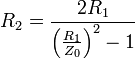
When Z=50, R1 and R3 equal…
![]()
[292.4 ohms].
Now R2 equals…
[17.61 ohms]
Well that was a pain. Luckily, there’s a cheat sheet for this.
So now we have our values, and assuming a 50 ohm load everything should work just fine. But wait! Somebody F*cked up and put a 300 ohm feed line on the end of the pad! Crap. Let’s look at the resistance values of the network now, from A to ground. I’m assuming you should know how to calculate resistances…

…105.7 ohms. That’s near double the 50 ohm input impedance and is going to wreak all hell upon the other circuitry. Sure, it does its job of reducing the signal 3dBm but still.
Now here’s the neat thing. Let’s pick some new resistor values so that we attenuate by 10dBm, or about 90%. According to our cheat sheet we’d need 71.75 ohms of attenuating resistance and 96.25 ohms to ground on either end. What’s the impedance mismatch now?

57.78 ohms, or 7.78 away from 50. That’s a lot better than before, and should actually be usable as an impedance matching network. Sure, you lose 10dBm or about 90% of your signal strength, but that’s nothing that can’t be compensated for by putting a Class-C amplifier in series with the attenuator. Even with an active component it’s still cheaper and smaller than a transformer. What I’m trying to prove here is that pi pads can be used as the poor man’s impedance matcher; as attenuation goes up the impedance mismatch goes down.
What’s nice about resistive pi pads is that they are ultra-wideband; since there are no reactive components this network will always attenuate by 10dBm and always match the impedance by 7.2 ohms. An inductive network such as a transformer might not work at both 200kHz and 200MHz. Actually, it certainly won’t work! Capacitive networks would have the same limitations.
</ LESSON>


Some of the images are giving me a 504 error fyi.
Why is your comment made of memes ._.
The formula images are nigh unreadable in Firefox…
not sure about other browsers.
Same here. This is one of the most bugged articles I’ve seen in a while..
same here. Can’t make it all out.
They need to invert the color of the equations. They’re meant for black-on-white text. The white outline we’re seeing is the anti-aliasing.
Pasted from Wikipedia? :) Although I’m sure that’s permissible.
background-color: #fff; would also do the trick :P
I enjoyed this article and would like to see more articles in the electronics theory/applied electrical engineering genre.
What does ‘A minus 6’ mean in the 2 pictures?
50 to 300 Ohms require at least 13.4dB attenuation.
And you need 0.1% resistors for a 16% (mis)match?
Use E12 ;-)
56
270
33000
Oh come on, a 50 ohm coax will work VERY well for a TV, it will give you a loss of 0.2 dB, SWR 1.5 . That is MUCH less than this attenuation network.
For a real impedance matching you need a pi network however not with resistors but with inductors and capacitors.
they mentioned an rg58 coax. this is not good to use for TV as it has basically no shielding and will pick up every bit of interference in the area. trust me its the reason my TV sucked in my house til I went in the attic and saw it was rg58.
Reading the title i expected a raspberry pi powered tablet!
This was also very educating. Some time ago i was talking about a speaker setup with a 200watt amplifier and a 300 watt speaker setup. Someone told me i should use a 300 watt amplifier or else i would blow it up. I told him that wasnt true for watts. Am i right?
You won’t “blow” anything with that setup IF and ONLY IF your impedance are matched. If you’re running 4 ohm speakers and an 8 ohm receiver, all bets are off.
you are right. when you meet him again tell him the output wattage varies with the volume of the stereo so that by his reckoning the stereo would blow up if he turned the volume down.
Yes driving a speaker capable handling 300W with an amp that delivers 200 W is not a problem, assuming both have the same characteristic impedance. Driving a 200 W speaker with a 300 W amp wouldn’t be recommended in any instance.
that’s like saying you shouldn’t drive in a car with 100mph top speed on a road where the speed limit is 60
Well that’s not strictly true either. If you have an underpowered amp and you attempt to overdrive it to get some volume out of some capable speakers you’ll typically end up with hard clipping. That could very well mean the end of tweeters and even some mid-high range drivers in your speaker despite not being anywhere near the rated power.
I always wondered, as both capacitors and resistors provide impedence, are there applications where capcitors are used in impedence matching as well?
Most real matching networks use inductors and capacitors. Resistors are not used most of the time, unless they are absolutely necessary (special cases).
Resistors dissipate a large amount of power (real impedance)
Inductors and capacitors store the energy and dissipate a small amount of power (imaginary impedance)
yes you can match impedances with a network of capacitors and inductors. It doesn’t have the loss of a passive resistor match, but it has to be designed, and only works, in a small frequency band
Ach noo,
wheres the raspberry pi content the title tempted me with :*(
Don’t let the volume go below 50mph or the stereo will explode… lol
I was pretty disappointed this was not a raspberry pi tablet build. Maybe a little less misleading title next time HAD.
I was truly happy it was NOT a RasPi article since that board is guaranteed to become the next Arduino craze, without sharing 10% of the Arduino openness.
Dude, you need to brush up on the difference between dB and dBm. Minimum loss pads are useful for broadband impedance matching when you are trying to reduce ripple, lets say at the end of a long cable run, or on either side of a filter to ensure good stop-band rejection. They are usefull where power, noise, or efficiency are not an issue; around the 0 dBm level. You certainly would not use a class-c amp to compensate for the loss since they have poor gain, rather a broadband gain block. If the values for a PI network are impractical then use a T network. Even with SMT parts these are usable only to a few GHz until the parasitic C limits your isolation.
Also wanted to add that impedance mismatch isn’t necessarily going to blow a PA. In some cases your dissipated power may actually decrease. Sort of like plugging the suction on a vacuum cleaner reduces motor current even though it sounds like the motor is going to die. But if your amp is folding back or shutting down due to mismatch, by all means insert a pad, that will at least allow the amp to operate with a reduced signal into a poor match, rather than not operating at all.
Re: “you’ll be wondering why your RG-58 antenna feed line doesn’t give you anything good to watch”
Having nothing good to watch is a problem regardless of the antenna feed.
And I thought this was going to be an article about how someone connected a large-ish LCD display to the Raspberry Pi,slapped on a battery pack,and called it the ‘Pi Pad’ :-P
me to you should find one of those to post about
I would prefer a less vulgar write up myself. Do we really need the language?
agreed.
First more stuff like this.Generally speaking when it come to reception matching impedance often isn’t worth the effort unless the received signal strength is extremely weak. When it comes to linefeed, feed line can be used to match impedance, but may not be as broadband as one may wish. The transmission line section of the ARRL Antenna Handbook is very informative in that regard, but I can’t find similar info online. I would think that the US Marine Corp Antenna Handbook would have similar info, but I’m not in the mood to sift through 197 pages. I just put it up at archive.org so anyone is welcome to looks. I’m pretty sure that this NEETS module would have it http://archive.org/details/Module10introductionToWavePropagationTransmissionLinesAndAntennas Reminds me that I need to finish uploading the NEETS modules.
USMC Antenna Handbook can be found here (not sure if current or not, but not much changes from year to year when it comes to antennas): http://www.zerobeat.net/r3403c.pdf
Wonder if something like this would work for converting bipolar TMDS signals to a single wire for sending HDMI over a 5 pin USB connector?
I am also working on a version of this using TOSlink, same idea but using 4 LEDs at the transmit end and 4 modified laser diodes alloyed together ranging from infrared to UV as the receivers.
Using the selectivity of the diodes to ensure that the correct signals get to the correct inputs..
Compute the minimum-loss L-pad first, it is simpler, and you can’t make a less lossy pad between two different impedances so you need not cut-n-try like is suggested here.
I thought this was going to be about a combination of the Raspberry Pi and the iPad
Im sure there is a simpler way. Way back when I was at university we were talking about matching impedances and with RF the best way to do it was via a bayron converter (correct me if im wrong here) which is essentially a torroidal core with a number of wraps to match the impedance. Its whats used in the tv Y splitters. to match the 100ohm of two lines to the 50ohm…. I will have to dig out the papers on it later!
Nice writeup, but it would have been nice to explain the math a bit more. I have a degree in Electrical and I can’t make heads or tails of your math without doing additional research. Now I know you’re going to say, “but if you work with RF, you wouldn’t need the added explanation”. True, but not everyone specializes in RF. If possbile, please explain what all of the variables are and show us the values you plugged into the equation so we can see how you arrived at your answers. If it were me submitting a lab report I would have to do the same…