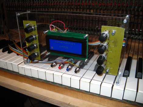
Update: Many Improvements To Optical-sensor-based Piano

[Sebastian] wrote in to update us about the optical sensor project he started a couple of years ago. You’ll find his most recent update here, but there are four different post links after the break that document various parts of his progress.

You may not recall the original project, but he was looking to add resolution and sensitivity to the keystroke of an electric keyboard. With the sensors built, he started experimenting with using the force data to affect other parts of the sound. His post back in January shows this bending the pitch as the keys receive more force from the player.

In March he installed the sensor array in an old piano. The video he posted where he plays the piano, but we hear the sound generated from the sensor inputs. We’ve embedded it after the break.

Last week he published two posts. They cover a redesign of the sensor boards, and the panelization work he’s done to help bring down manufacturing costs. The base unit was redesigned to use an AT90USB microcontroller which consolidates the separate chips used in the previous version.

Continue reading “Update: Many Improvements To Optical-sensor-based Piano”

Chibikart: Step-by-step Lets You Build Your Own Tiny-wheel Racer

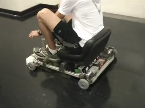
[cHaRlEsg] posted a rant, then posted full instruction on how to build this electric go-kart for yourself.

Now the rant calls this an unobtainium-free sibling to the Chibikart. We’re sad to report that the unobtainium he’s talking about are the hyper-awesome hand-wound hub motors that powered the original kart which left us dumbstruck after seeing it for the first time. But look, few mortals have the skills and tools necessary to manufacture those circular marvels of modern engineering.

So you’ll just need to settle for stuff you can buy to assemble the tiny kart seen here. It’s all-electric, using two DC motors to power the rear wheels. You can catch it racing around the hallways in the video after the break. The only thing we can see missing from the equation (other than red shells and the like) is a helmet and bumpers (you’ll see why at the end of the clip).

Continue reading “Chibikart: Step-by-step Lets You Build Your Own Tiny-wheel Racer”

This Is Not Real: Lifelike Renderings From Eagle Files

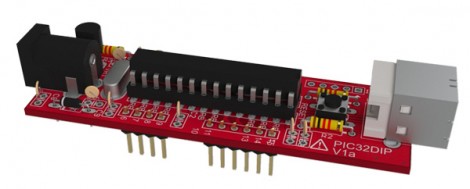
Look at it. Just look at it! This board is a lie. It doesn’t exist (at least not what’s seen in the image here). Instead this is a lifelike rendering made from Eagle CAD files.

We’ve already seen that it is rather easy to pull Eagle CAD files into Google SketchUp thanks to the EagleUp package. You’ll get a 3D model that looks quite nice but it’s hardly photo-realistic. This process starts exactly the same way. But you’re going to want to process the SketchUp file one more time.

A program called Kerkythea does this for you. It’s an open source project aimed at producing realistic renderings. It has a plugin which will process any SketchUp model and apply the textures and shadings that look so wonderful in the image above. It’s not a one-click process, but reminds us of the mountain of options you’d find in a program like Blender3D. You’ll need to map out settings for each different material you’d like to map, but the guides found at the link above do a good job of showing how it’s done.

Simple Power Adapter Thumbs Its Nose At Proprietary Connectors

[Mike Worth] wanted to use his camera for some time-lapse photography. Since it’s used to take many pictures over a long period of time, he doesn’t want to deal with batteries running low. But there’s no standard power jack on the side; instead the official charger consists of an adapter that is inserted in place of the batteries. Rather than break the bank with the special cable, [Mike] made his own battery compartment A/C adapter.

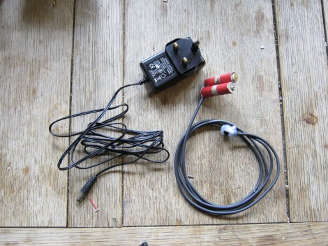
You can see that it is made up of two parts. The first is a standard wall wart that outputs the correct voltage and has an acceptable current rating. The other part is the adapter cable that connects to the camera on one end, and has a barrel jack on the other. [Mike] rolled some paperboard around a pencil until it matched the diameter of a AA battery. Once of the cylinders has a thumb tack for the negative lead, and the other uses a screw and washer for the positive side. He soldered some wire to these and he’s in business.

He must be snapping photos frequently enough to avoid the auto-shutoff feature. That or he’s disabled it with the use of some custom firmware.

Open Hardware Moodlamp With ATmega

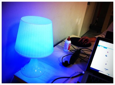
[Daniel Andrade] has built a pretty cool mood lamp circuit. He was initially inspired by [Toon Beerton’s] Ikea lamp, but found he just didn’t have the knowledge to proceed with the PIC processor. He rushed out and bought an arduino to begin learning. Once he figured out how to properly make a mood lamp function, he created a custom circuit to utilize an ATmega chip instead of his whole arduino.  He’s now on his second revision of the circuit and is sharing all the files with whoever would like to download them.

His circuit utilizes a 3wRGB LED and any ATmega 8/168/328. He has left some space for expansion on the board as well just in case you’d like to add sensors of some kind (he mentions a temp sensor).