In addition to being a serviceable single board computer, the Raspberry Pi also has a header full of GPIO pins at your beck and call. [Tedbot] sent in a great tutorial on using these pins with Python, Bash, and C.
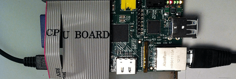
The GPIO pins on the Raspi are arranged in a 2×13 header. Until Sparkfun manages to manufacture a decent Raspi protoboard, the easiest way to break these pins out is with an old IDE ribbon cable. After plugging the other end into a breadboard, [Tedbot] had an easily accessible set of Raspi pins.
To control these pins, [Tedbot] found two libraries: the first is WiringPi that implements a C-style, Arduino-like programming environment on the Raspi. The second is the RPi.GPIO Python package. Since the Raspi runs Linux, and everything in Unix is a file, [Tedbot] used a shell script to blink a LED.
One word of warning if you’re building a board to extend the capabilities of the Raspi: these pins aren’t 5 V tolerant, so you’ll need to throw in a buffer or level converter when building a Raspi circuit.
Edit: Adafruit is releasing a Pi Plate prototyping board in a few weeks. Neat, huh?


Adafruit already has a prototype board for the Raspberry Pi:
http://www.adafruit.com/products/801
Oops, I mean they’re testing it. They also have a nice transparent acrylic box.
Don’t know if SparkFun is working on anything.
We have a nice Acrylic box already :-P
http://www.ebay.co.uk/itm/Laser-Cut-Acrylic-case-for-the-Raspberry-Pi-/251078653815?pt=UK_Computing_Case_Accessories_Tool_Kits&hash=item3a75743777
[youtube http://www.youtube.com/watch?v=1rlYz2wI7hY&w=560&h=315%5D
I just want to know if anyone has an idea of how to connect an IR module such as TSOP 1738 to the board using the GPIO and LIRC drivers.
Dragon,
The RPi doesn’t have an ADC, so you’d have to use an external one connected to SPI or I2C. Then you’d have to write code to interface with that to take readings, then you’d have to interface with LIRC. So, if you just want to read from an IR remote, you’d probably be better of using an off-the-shelf USB module.
wait what? why would you want ADC for a digital signal?
Oh! Whoops, I didn’t look closely enough; I hadn’t realized it was a digital device. Nevermind about the ADC! But you’d still have to write the code to demodulate the output and get it talking to LIRC.
Check out this lirc driver for the raspberry pi : http://aron.ws/projects/lirc_rpi/
There are probably already code examples in the wild to bitbang lirc, shouldn’t be that difficult to port.
I wished they open sourced their hardware. That way us United Stateans can buy a clone or something.
It would be great to have their designs, but the schematics are only part of the equation. The supply chain is the real hard part; even with the schematics there’s no way we’d be able to get the price close to $25.
I thought the Raspberry Pi company went bankrupt or default or something, this things actually exist?
(Sarcasm above.)
> the easiest way to break these pins out is with an old IDE ribbon cable
Seriously?
IDE ribbon cables have over half their conductors as ground, including a few that are mapped to actual pins, and all those ground conductors are connected via a conductor in each of the connectors.
Plug an IDE cable in to anything that isn’t designed with those ground cables in mind and you will short some of your pins… which is usually a good way to annoy your hardware.
There are also a couple of pins that aren’t connected at all in one of the connectors, and a keying pin that is blocked up just to make your life fun.
http://en.wikipedia.org/wiki/Parallel_ATA#Differences_between_connectors_on_80-conductor_cables for full details.
Huh, never knew that. Crazy. In this case, it’s a totally plain IDC ribbon cable connector, no special wiring. Obviously safest to crimp your own. I tested all the pins for funny business before powering anything (3 times), as I always do. I’ll add this information to the tutorial. Thanks!
The newer higher speed IDE 80 wire cable is the one that has every second conductor grounded, the older 40 wire cable does not. And it’s easy to tell the difference – just count the conductors in the ribbon cable!
not the really cheap ones. only ide-80 not ide-x25.
I want to know if its possible to connect an old eide/pata cd/DVD drive up to my raspi to play movies and such.
Any suggestions?