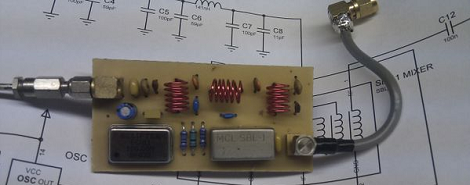
[regveg] was looking for a way to receive signals outside the normal 64-1700MHz range his TV tuner software defined radio dongle can get. After finding a few $100+ upconverters on the Internet, he stumbled across a DIY project that greatly expands the frequencies his RTLSDR can receive.
[George]’s upconverter uses heterodyning to increase the frequencies received by a SDR dongle. The basic idea is mixing a signal from an antenna with a 100MHz frequency oscillator. The resulting output will be λ + 100MHz and λ – 100MHz, allowing for a wider range of frequencies that can be received by the SDR TV tuner dongle.
Now [regveg] has a board and schematic that makes it possible to receive just about anything with his TV tuner dongle. Interestingly, this upconverter contains less than $10 in parts and is easily etched at home thanks to a single-sided construction and through-hole parts.
As a small aside, [Andrew] sent in a tip a few days ago telling us his RTL dongle didn’t have any ESD protection. This is a very bad thing, but the good news is the fix is very cheap: just solder in a 10 cent diode and you’re good to go.


I hate doing this…
“…frequencies to you software…”
“…frequencies to /your/ software…”
If you’re wondering why this post went up so late on a Sunday night, it’s because I was editing it. I transposed RTLSDR into RTLDSR, something I know would have caught a ton of flak.
Our readers our the best editors, it seems. Thanks.
are*
trolol
Crowdsourcing man! Free services! Great results! Smart cow problems!
http://en.wikipedia.org/wiki/Smart_cow_problem
“Sh*ts Awesome!” as much as it is “Annoying!”
Trolling is a art!
an art*
I was wondering when someone would write about doing this ;)
Great trick that beginners might not know about.
This is the same basic way a Superheterodyne works.
If your cheap SDR only covers from [say] 64MHz, then you may be better off using a 64MHz oscillator. That way, even if the oscillator bleeds through to the output, it won’t affect the RTLSDR so much.
If you use something like the Si-570 I’d suggest 63.5MHz to be even safer.
But then you would cut off vlf-mf… if you are interested in that…
Take a look at Tony Parks (KB9YIG) Softrock EnsembleRX sdr board for some more inspiration. http://www.wb5rvz.com/sdr/ensemblerx/
4 channels and local oscillator switchable via USB
160m – Continuous coverage from 1.8 to 2.0 MHz
80m and 40m – Continuous coverage from 3.5 to 7.3 MHz
30m, 20m, and 17m – Continuous coverage from 10.1 to 18.168 MHz
15m, 12m, and 10m – Continuous coverage from 21.0 to 29.7 MHz
I was playing around with redesigning the board for it in GEDA for fun. I’m still not done with the schematic but I haven’t been working on it recently.
Oops.
I meant to link to the EnsembleRX II
http://www.wb5rvz.com/sdr/ensemble_rx_ii/index.htm
I really haven’t looked at the earlier Softrock. It figures the section I want to mess with is the analog portion of the board, where it’s all probably voodoo and the slightest change will wreak havoc if I ever build it.
It’d be neat to add in VHF and UHF to this, as well as the 4 bands of LF added in this revision, but you get that for free with the TV tuner USB dongles.
Obviously there’s going to be adjacent channel interference using this method, but it’s a hack and it works.
I’d recommend to use a special ESD protection diode instead of a small signal diode.
Less capacitance and better ESD protection.
The BAV99 is a low cost component, that isn’t even ESD rated.
Better use a PESD5V0F1BL or such.
KC9ICS here. Nix the diode. Unless you want to pick up the powerhouse FM and now TVnoise as “birdies” all across the band. In a word, INTERMOD.
I once tried out a rat shak scanner on the “public band” FM 88-92 mHz, this scanner could get everything in it’s day. It couldn’t get the good stations and had the locals from above popping up allover the band. 88.1 was a mess, at least 4 locals were intermodulating together. So I would like to know how one of these dongles does even on broadcast FM. The reference tuner is just a Pioneer Supertuner car stereo at home, on a beam antenna. I have made a spectrum analyzer out of a similar performance radio. It would tune up into aircraft band. Because it is clean as tuners go, it displayed every bit of noise or station clearly on the scope, with none of the smudges of intermod mucking up the display.
88.1 is pure chaos here in Chicago. The FCC licensed just about every College, High school and church in the city and suburbs. Well I exaggerate a little, its only 17 stations.
Heheh, back in the mid ’80s I was at one of those stations and one night something in the ancient transmitter we were nursing along decided to let out its magic smoke, and we started to drift left of the dial. Got a nice call from one of the local hams to let us know, and a less nice call from the FCC. Thanks to the ham, we were already shutting down. Glad I wasn’t engineer that night, I was on the other side of the glass.
@Cyk: BAV99 is the one, that can be found in the original reference schematics for E4000 tuner. Anyway, thanks for the tip – I’ll go get a few right away!
E4000 bandwidth is 64MHz up to 1700MHz. It’s capable of working from 50MHz up to, say, 2100MHz. It works fine at lower frequencies, above 2GHz sensitivity gets lower.
I connected Funcube Dongle PRO to AM IF of TECSUN PL-600 (55.845 MHz). It works great :) RTL-SDR works fine too, however to improve sensitivity it would require a preamp.
Hi,
Please could publish the schema of the output IF 55.845 – Tecsun PL600?
Thanks
I am working on improving this with a notch filter for 100MHz, to reduce leakage. 100MHz was chosen because it’s easy to back calculate the input frequency from the up converted output. A simple LC circuit would remove it. I will try and make a new board with better filtering. Time depending, of course :-) cheers folks.
If you’re going through this much trouble, might you go Full Monty and just build something like a Tayloe Detector?
That’s interesting. I’ve seen that idea before; the softrock things too. I may well design a board for those too. For an inductor and a capacitor, it would greatly improve results.
The $0.10 solution is better for the E4000 usb stick. One simply bypasses the VHF front end to use the AD chip in raw sampling mode under 34 MHz.
It works fine for local stations.
like the so called “fm booster” you could get in the 70’s and 80’s that allowed you to get fm on an am only car radio
Similar but not quite the same. I assume, I really hadn’t look it over well yet, this is block converter. The FM broadcast band converters where tuners that had an output on a single frequency in the AM broadcast band, not a block converter. The AM broadcast band doesn’t have enough bandwidth to be able to block convert the entire FM broadcast band to it. I had a unit that I used over 3 personal vehicles. I could have used it in work vehicles that had AM only radios, but never did. Why I didn’t don’t know.
Doesn’t this thing need to be in a metal case? Or at least have a grounded metal edge the height of the components around it.
I’m going to use a metal enclosure for both the upconverter and the dongle, as well as build a smoothing circuit (few caps, ferrites) for the 5v coming in as I suspect this will be pretty noisy coming from my pc.
Ah, so it’s a work in progress thing, understood.
Still hard to judge what tweaking it needs if it isn’t tested in a grounded enclosure I imagine though, or is it? Although the PCB is nicely done with its professional maximized grounding I have to say, although I hear using SMD components really helps with such devices too, but that’s so damn fiddly though, still, a SMD resistor has so much less pickup than a classical one for instance, since it doesn’t have the legs that work as an antenna.
But redesigning/rerouting it seems excessive when you hare something that works, so take my remarks as a general rambling.
This link is dead: http://ncrmnt.org/wp/2012/06/30/rtl-sdr-static-protection/
The SDR Protection.. Anyone have a mirror?
I have been searching for the SBL-1 mixer to build this circuit, but have been unable to locate anything other than the SMD version that is available on E-bay.. has anybody had any luck locating this part?
I found it here: https://www.minicircuits.com/MCLStore/ModelInfoDisplay?13538334035840.8858885910124503
But at $8.00 each, ouch. Need to find a cheaper replacement.
is there a kit or fully assembled version