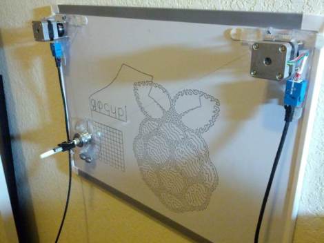
This polar graph draws some amazing shapes on a dry erase board. Part of that is due to the mounting brackets used for the two stepper motors and the stylus. But credit is also due for the code which takes velocity into account in order to plan for the next set of movements.
The Go language is used to translate data into step commands for the two motors. This stream of commands is fed over a serial connection between the RPi board and an Arduino. The Arduino simply pushes the steps to the motor controllers. The inclusion of the RPi provides the horsepower needed to make such smooth designs. This is explained in the second half of [Brandon Green’s] post. The technique uses constant acceleration, speed, and deceleration for most cases which prevents any kind of oscillation in the hanging stylus. But there are also contingencies used when there is not enough room to accelerate or decelerate smoothly.
You can catch a very short clip of the hardware drawing a tight spiral in the video embedded after the break.


Nice project and great execution. How did you do the conversion from pictures (raspberry pi logo and face) to vector line art/gcode?
Oh man I was just about to start a project just like this. Well done people!
Here you go Peter
http://www.makerbot.com/blog/2012/03/12/single-line-art-traveling-salesman-problem-tutorial/
That stepper driver looks tiny. I’m impressed it can do such fine microstepping. What driver is it?
http://www.schmalzhaus.com/EasyDriver/ I got them from spark fun, its running at 1/8 micro stepping and the motors are 200 steps per rev
Thanks! Last time I had a easydriver it overheated and burned out. Did you have this trouble too?
I put a small heatsink on it just because I had a bunch sitting around, but I haven’t had any problems, even when I accidently ran it at max amps instead of min for a few days because the labels on the PCB for the version I got are backwards
Any links for schematics, BOM’s etc? It looks like you breadboarded an arduino but not sure about the motor drivers and pinouts from the Pi. Thanks!
For schematics I just used the gertboard manual which details how to hook an arduino up to the pi. The stepper drivers are easy drivers from spark fun, more info for them is at http://www.schmalzhaus.com/EasyDriver/
Does anyone know which of these drawing robots are open source? I think it could be feasible to build one with multiple heads for simultaneous writing but I’d rather start on a good foundation instead of rolling my own.
Sandy Noble’s polargraph is OS. Download source from here:
https://code.google.com/p/polargraph/
Sweet, I saw the main page for Polargraph but couldn’t find the good stuff, thanks!
Why use an Arduino? Surely you can use the GPIO pins on the Pi to driver the steppers?
At full speed with 1/8 micro stepping there is a pulse roughly every 400 microseconds. Since the pi is isn’t running a hard realtime OS it can’t guarantee that the polar graph process will be running constantly, and a user land process doesn’t easily have access to timing that is microsecond precise
But that doesn’t matter. A stepper motor will either take a step or not. As long as you don’t send the pulses too often then you can run it as slowly or as fast as you like. The key is to synchronise the pulses sent to the X and Y steppers, but even with a little latency I don’t think this would be an issue. If it was, you could probably just use a 4042 latch and set up the step/direction state for both motors, then a single pulse would synchronously transfer these signals to the output.
Maybe I’ll have to build one myself to find out. That’s why I’m interested in this project, it’s one of the best ones I have seen.
Why use a raspberry pi, you could hook up the arduino to a laptop ?
Why use a laptop or motors, just make knobs and twist them to draw…..
Dan Royer at MarginallyClever.com has a nice open Java and Arduino project that’ll even make your photos into G-code.
Use three, or four like those flying cameras, motors and there’ll be no oscillation or wiggle or wobble problems.
Do this on a whiteboard in a classroom somewhere, and then take it down and hide it. When someone comes in, grab the marker and pretend that you did it by hand. Minds will be blown. Lulz will be had.
It would be nice to have some information about the pen.How is made the system that move the pen away from the board when moving and not drawing ?
The pen always touches the board. You can see in the first photograph. There is no system to move the pen away from the board.
guys its awsome can i have the software link for raspberry pi board