Thermal imaging cameras, cameras able to measure the temperature of an object while taking a picture, are amazingly expensive. For the price of a new car, you can pick up one of these infrared cameras and check out where the drafts are in your house. [Max Justicz] thought he could do better than even professional-level thermal imaging cameras and came up with an absurdly clever DIY infrared camera.
While thermal imaging cameras – even inexpensive homebrew ones – have an infrared sensor that works a lot like a camera CCD, there is a cheaper alternative. Non-contact infrared thermometers can be had for $20, the only downside being they measure a single point and not multiple areas like their more expensive brethren. [Max] had the idea of using one of these thermometers along with a few RGB LEDs to paint different colors of light around a scene in response to the temperature detected by an infrared thermometer sensor.
To turn his idea into a usable tool, [Max] picked up an LED flashlight and saved the existing LED array for another day. After stuffing the guts of the flashlight with a few RGB LEDs, he added the infrared thermometer sensor and an Arduino to change the color of the LED in response to the temperature given by the sensor.
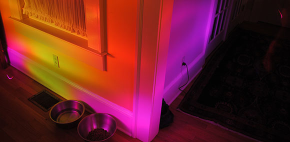
After that, it’s a simple matter of light painting. [Max] took a camera, left the shutter open, and used his RGB thermometer flashlight to paint a scene with multicolor LEDs representing the temperature sensed by the infrared thermometer. It’s an amazingly clever hack, and an implementation so simple we’re surprised we haven’t seen before.


This is definitely a brilliant idea!
And you can also have some sort of realiltime indicatio, if ony for a spot.
wow, what a genius idea.
1) i’m surprised at how uniform the light painting is! must have had a steady hand?
2) that RGB flashlight is absolutely bad-ass even on its own!
3) referring to #1, a cool followup project might be to mount it on 2 servos so that it can ‘auto-paint’ the room.
Inre: 1) Maybe the bright bars on the wall right of center are the actual scan readings and the darker areas are just LED “overspray”?
downside of course is you need to be measuring something white but still very clever.
Perhaps converting the image to grayscale and repaint it with the LED value(s)? Some compensation would need to be made for dark surfaces, maybe instead of grayscale, use edge detection/extraction and repaint?
Or, y’know, he made a functional device that works pretty damn good using scrap supplies. It shows a general temperature difference in the photograph.
@Kyle, I wasn’t demeaning his awesome work, a dark surface may be a problem and I was offering suggestions to possibly overcome that.
Actually, due to variations in emissivity, an infra-red thermometer needs to be re-calibrated for different surfaces in order to produce an accurate result. A matt black surface is usually ideal. The fact that the LED lights don’t reflect from a matt black surface (I doubt that rug was colder than the walls) just compounds the problem. I wonder to what extent the light shining on the wall feeds back into the device (could be none at all for all I know). I think this hack makes interesting pictures but I’m doubtful of its practical uses.
Wow, that’s excellent. I shall have to make one of my own. That is a great idea you have come up with!
Simply amazing! There should be awards for these kind of things! No god damn design prize, **** industrial designers that invent new problems. This is how its done.
He was working off someone else’s idea. yes, he made the breadboarded project a reality and its pretty neat, but I don’t think you generally get awards for that.
Awesome hack!!
Version 2.0? – Kinect + IR thermometer + auto applied heatmap over image.
Benefits!
1) The IR thermometer’s “range cone” (10:1, 50:1 etc) can be accurately measured to appropriately calibrate the heatmap.
2) Target surface color is irrelevant
3) its automatically digitized, so no additional camera needed.
I was thinking almost the exact thing.
You have to also take into account that the IR beam is a spot in these meters, on mine it says 12:1 ratio for the distance vs spot size, meaning at 900mm distance the spot is 75mm etc. So finding a small leak might not be as easy with these.
Nevertheless a very good idea!
Meant to say: is NOT a Dot in these meters…
But maybe you can mask it or use a lens to focus though.
Cool, yes! Practical for the purpose it was designed for? No…
The room you are trying to image would have to be perfectly dark, not always possible.
And the room colors will also screw with the results.
I’ve not deeply looked into it yet, but I think you could do this in far fewer parts:
The sensor has a PWM output mode. If we buffer that with a NPN (not sure how much current it’s meant to source/sink) and have two LEDs, one to ground, one to +V, the LEDs will crossfade based on the temperature detected. It’ll probably look flickery to the naked eye, but will look “right” in the end exposure.
Good idea, nice project. Even some room for improvement :) The light painting is not something someone can learn to do in a sec, and you probably need a tripod for it. What about making a lot of pictures with one temperature reading attached. then you let the magic software overlay these pictures into one. That will give you a XY coordinate in which direction each reading was taken, which can be converted into a visual picture to overlay on the original picture. You probably need quite some processing power for it, so it may be that you cannot display it real time on the camera itself.
In other words: the (analog) light painting part of it is a nice hack, but you do not really need it per-se.
Something like Photosynth?
Been done before, the same hack from over a year ago:
The Thermal Flashlight
http://publiclaboratory.org/tool/thermal-photography
Pics:
http://www.flickr.com/groups/thermal-flashlight/pool/with/6502706317/#photo_6502706317
What’s the response time on these sensors?
If you built an optical system that swept up/down & back/forth… couldn’t you do this in real time… essentially eliminating the long exposure camera step?
AFAIK the update speed of those devices is limited, but I’m not sure that is the sensor’s fault.
$49 from Black and Decker. http://www.blackanddecker.com/power-tools/TLD100.aspx#
Cheaper than an Arduino and some LED’s.
That is just a handheld thermometer as used as basis of this hack.
Not really;
It’s a similar idea; it’s basically a Red / Blue / Green (? can’t remember) flashlight that illuminates an area with color based on the temperature. That device is pretty primitive in that it only gives one of three colors based on a baseline (green = cal temp, blue =-10 deg, red = +10deg). It allows you to quickly find hot / cold spots in a room without having to constantly read the temperature display.
Quite clever, and pretty similar concept.
Amazing, if that could be servo’d, it would give the competition a real run for their money.
In fact, you could also collect the temp data and then plot it afterwards to solve the colour issues raised above
This is a great mix of light painting and hacking.
Great way to start off the year HAD!
I love this project. So sexy. The other projects that were done before, also sexy.
Combine a POV display system with the thermal sensor and RGB LED output. Put the thing on a linear actuator with a position sensor.
Have the actuator extended, fire up the spinny bit then slowly retract the actuator. Use the POV system to turn off the LEDs when they would be shining out of the camera;s view.
Alternate method, combine with a 360 degree camera and use a simple spinning rig for the sensor and LED.
That’s both obvious and old tech really, instead you should use an accelerometer to determine where it’s directed at and compile a picture after swinging it around a bit :)
Add a cam to also compile a visual picture and voilà.
REAL HACK. nice job creator!
Accelerometer would work.
For those folks who have a PIR sensor but not an infrared thermometer, a simple pager motor based interrupter could work and in fact obtaining a “flat” motor as used in those cheap phones and simply drilling and deburring a hole being careful not to hit the windings would be a compact modification.
It might also work (badly) with the little LCD screen from a PS3 or 360HD drive, it will attenuate a lot of heat but work somewhat.
FInd an old broken security light in the WEEE Bin and hack away!
how about a Nipkow disk camera and a Non-contact infrared thermometer?
https://www.youtube.com/watch?v=D-yO07MQPMA
action from 3:14
Might work.
Interesting aside: many “cheap” oven thermometers intended for cooking are deliberately crippled so they won’t read below 50 Celsius or over 250 but its probably feasible to edit the 24C02B e2prom if present if the value boundary locations can be found. Its the same sensor as more expen$ive units.
Watch out though as some hide a calibration button next to the power button and if this is accidentally pressed it can be hard to recover the correct values.
Also possible is reading the LCD over/under range indication to use these for other applications as its a specific pattern easily seen on say a suitably programmed microcontroller.
Modifying the LCD driver as seen here https://forum.arduino.cc/index.php?topic=57550.0 allows this to work on any oven thermometer with a display.