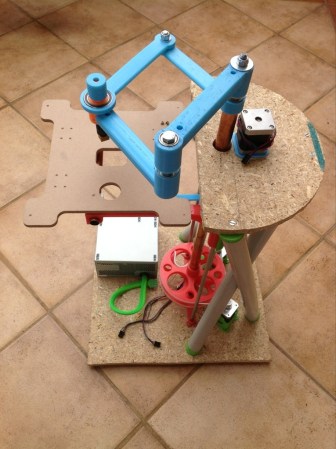
[Quentin Harley] must really have wanted to test his snuff when it comes to mechanical engineering. He’s been hard at work for a couple of years now designing his own SCARA arm 3D printer. That link leads to a recent summary article in which he shows off the build as seen above. It’s not fully functional yet, but he’s at the point where it’s time to develop the driver circuitry and firmware so he’s close. His blog is dedicated to this single project so click around and see what he went through along the journey.
The SCARA arm is seen in blue, using a couple of stepper motors to move the extruder mount along the x and y axes. The bed itself moves along the Z axis via two precision rods with a threaded rod in the center. As you can see, some of the parts are made of wood, and he used PVC for the cross supports between the upper and lower base platforms. But the majority of the build uses 3D printed parts, including the arms, drive gears, and mounting brackets.
[Thanks Peter]


>robot arm
>open loop control
that does not compute bro.
Open loop works if you use steppers where the amount of movement is defined. Stricktly speaking is is not quite open, but you don’t require feedback.
and what about missing a step?
Yes, that is always possible. You have to design your system in such a way to make step skips unlikely.
Morgan is no heavyweight tool swinging cnc or pnp. The motors are also driven in microstep mode, making skips highly unlikely (given that the forcve required for movement does not exceed the motor torque at the selected driver current)
All of the RepRAP fdm machines currently use this control system, and is working just fine at the moment. Even the deltabot, Rosstock-by Johann Rocholl.
Why SCARA? Aren’t they designed to be compliant on X/Y? I wouldn’t think that would be good for 3dp.
Notice that the print bed can be raised and lowered. That’s how the Z-axis is implemented.
Soon… he will discover the math needed to run this thing accurately is impractical to implement with bad tolerances. He is not the first to fail at this design, but it is a nice build attempt.
Nonsense! SCARA kinematics can be implemented on a printer: There was a fellow who attempted it a few months back. http://transistor-man.com/3dprintbot.html
You can see the crazy sampling in this video.
https://plus.google.com/105705619434685566948/posts/MBCYNJQxhEZ
@lol
Thanks for your concers, but you will excuse me if I remain optimistic of my current design. You will know soon enough if I prove myself right (or wrong as it were)
Cheers!
Q
@quentinharley
You will need to get some real industrial servo control loops to get this type of arm even remotely accurate. These were common for 1980s pick-and-place DIP insertion because they could wobble the chip alignment to inaccurate PCB holes.
@nah
There are several designs over the years that failed to achieve even comparative results to primitive gantry based systems. Even $1700 worth of professional industrial servos won’t fix the problems.
Maybe you guys are more qualified than the other engineers that failed to get it to work properly.
Best of luck…
=)
Hi lol
Thanks. I will need all the luck I can get.
No, not more qualified at all, but living in an era where microcontollers run circles around any of the computers of the 80’s. This is hihgly unfair to those poor engineers that had to pioneer using the tools of the day, but I am not competing with them at all. Morgan is my pet project. I don’t care if it takes me 10 years to complete, but I have a feeling I am getting close. You should have seen some of the previous prototypes…
See you at the finish line ;-)
Hey Hackaday
This is unexpected. Thanks.
@lol
You will excuse me if I remain optimistic about the design… I did a couple of things differently than fellow SCARA hackers, and I would love to be the one proving myself right (or wrong…)
Cheers,
Q
I’ve been designing a SCARA arm myself too. It’s a different style with no “weak links” reducing the tolerance since both arms are driven directly from steppers via timing belts. It remains to be seen when this thing actually gets built… http://entropia.1g.fi/kuvat/Projektit/SCARA/proto2_2.jpg/_big.jpg
Nice.
There are always weak liks though… You will find yours when you start building ;-)
Perhaps consider “inverting” the mechanism so arms point inwards from driven concentric drums. Then little need for rhombus, same effect achievable with a “V” [from hinges on the drums, to the head]. accessible table size = circle that fits inside the drums. accuracy would suffer in the middle with a two arm design. add a 3rd drum&arm if that needs dealt with.
This sounds like a very interesting concept. Definately not unworthy of exploring.
There are odd CNC lathes that are designed this way, but without precise tolerances it still has numerous problems. One of the Rep-Rap builders attempted a similar design, and it just added a degree of complexity given each axis would deviate gamma on translational motion of other axis.
Perhaps you can steal some ideas from a silicon-wafer handling robot arm:
http://www.harmonicdrive.de/cms/upload/img.content/en/2_4_7_bg.gif
;-)
I like the concept of the link you posted, and one of my earlier prototypes followed that arrangent, but the weak link in this case is the weight, and the flexibility of the plastic – not a great combination for reprap. To bring cost down, I also needed to strip away some belt, and the toothbelt pulleys.
I currently only need two pieces of open ended belt, and two pulleys. The drive wheels are printable, and not toothed.
It looks like you are very experienced in the field of robots. Thanks for your inputs
scara and delta robots are the future of thermoplastic extrusion printing! I really like this one
I apologize in advance for all the glitchy typos in my replies. Smartphone.
Q
website is down (pbbly due to HaD exposure) any vids on third party sites we could watch?
Just checked. Looks ok. Check again?
chrome could still not connect to it….
1 1 ms 1 ms 1 ms 192-168-0-1.rdsnet.ro [192.168.0.1]
2 3 ms 3 ms 3 ms 10.0.0.1
3 3 ms 3 ms 3 ms 10.32.60.177
4 3 ms 4 ms 2 ms cr01.cluj.rdsnet.ro [213.154.140.0]
5 30 ms 29 ms 36 ms br02.frf02.pccwbtn.net [80.81.192.50]
6 134 ms 120 ms 119 ms vl0019.gwy02.sctn01.hostnoc.net [63.218.31.42]
7 117 ms 117 ms 117 ms xe1-02.agg01.sctn01.hostnoc.net [64.191.19.2]
8 123 ms 130 ms 121 ms ec0-42.bf2801.sctn01.hostnoc.net [64.120.246.126
]
9 * * * Request timed out.
10 * * * Request timed out.
11 * * * Request timed out.
12 * * * Request timed out.
13 * * * Request timed out.
14 * * * Request timed out.
Looks like you already featured this actual scara arm as 3D printer, but here is another link back to the awesome. I had the chance to get a talk with the guy behind it. Really cool guy.
http://transistor-man.com/3dprintbot.html
I managed to get SCARA inverse kinematics running on RAMPS with Marlin. Check out my new post…
Still needs some tuning, but it is doing exactly what I wanted for this point in the game!
Cheers,
Quentin
It is 2017, I’m optimistic to know the now.
Lots has happened since that first Hackaday post!
You can get the rest of the story at http://www.morgan3dp.com