This is something of a square peg in a round hole type of problem. [Kiel Lydestad] has been riding a vintage Moped around. You know, a motorcycle that can be pedaled like a bike. He of course wants to keep the thing looking stock, but also needs it to be fully functional. Enter this light bulb replacement project. His brake light needed a new bulb, and he managed to make this 12V LED bulb work in the 6V socket.
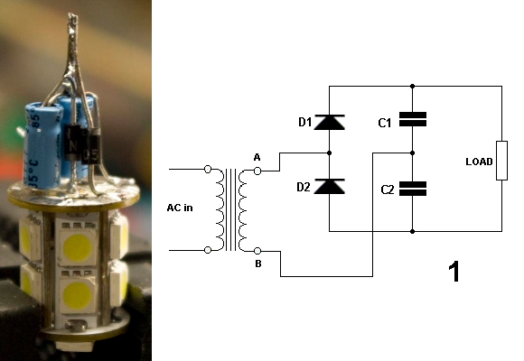
An LED is a really great choice for this application since the Motobécane Moped uses a magneto generator to power the lights. It won’t pull much current, but it did need modification to run from half as much voltage. [Kiel] mentions that it may have been possible to crack open the LED tower and adjust the current limiting circuit inside, but he felt it was easier to just add this voltage doubling circuit. He assembled the components in a way that still allows them to fit in the metal base of the bulb.


The current limiting resistor could have been changed, but with strings of 2 White LED’s in series, 6V isn’t really enough for proper operation, since White LED’s are usually between 3 and 3,6V
Hmm, clever, but a buck boost driver seems like the better way to go.
Also, where does the AC power come from? Isn’t a moped the same as those e-bikes I want to run over, ie DC power?
A moped is not an e-bike.
It has a MOtor (usually 2-stroke) and PEDals.
Not necessary pedals either.
Anyways, magneto generators in vintage bikes make very dirty power and they usually have simple zeners as regulators that shunt the excess voltage through a low resistance to ground. The output waveform is some sort of chopped up sine and the voltage sways a lot depending on motor speed and load on the magneto.
That is, if it has a voltage regulator in the first place. It may rely on just the magneto saturating out due to the load. It’s probably going to destroy the LEDs in a week.
Hi – owner here. The wiring of the Motobecane is pretty weird – there IS an AC regulator, but it is only used on the Headlight/Tail light circuit. The brake lamp is fed off of the low-voltage ignition magneto (same coil that feeds the points and HV coil).
Current levels have stayed within expected values under testing thus far (including high revving), so I think it will be okay for the moment.
You should check it with an oscilloscope, because while the RMS current may be fine, you will have large overvoltage spikes from all the induction noise in the system. The regulator is pretty dumb.
That said, the voltage doubler circuit you have acts as a lowpass filter of sorts which helps, but you have to be careful that you don’t blow out the capacitors instead.
That was something else I had noticed during operation. I measured the forward voltage drop around ~2.6 volts on each LED, and I suspected that I would only be getting illumination around the peak of the sine wave. A buck boost driver would have been ideal, but this was easy to implement, and is intended to hold me over until I fabricate an LED panel to fit inside the tail lamp housing.
Fortunately for you, the peak of the waveform is pretty flat. It’s probably at peak voltage about half the time. Here’s how the moped regulator works in principle:
http://home.comcast.net/~loudgpz/GPZweb/RegRec/GPZacRegulator.html
The main problem is that you get huge switching transients because the regulator is basically shorting the magneto coil to keep the voltage down. When it releases the shunt, the inductance in the system pushes a big voltage spike through like in a boost converter. That’s no problem with regular incandecent bulbs, but it will burn out integrated circuits down the line that aren’t filtered and regulated independently.
Also, 6 volt systems in old bikes and cars actually operate at 7.3 volts because the same regulators are designed to work with lead acid batteries that have full charging voltage of about 2.43 volts per cell. Three cells form a 6 volt battery with a voltage range of 5-7 volts.
Are they still though? All flashlights I see these days have 3 to 24! white LED and only use 3x 1.5V (or even the rechargeable 1.2V) batteries, and the ones I checked didn’t seem to have a bucket converter circuit.
Not sure what the ratings are but running 12 LED on three 1.2v batteries for a decent amount of time is not bad.
They still do require about 3 volts to reach full brightness, but the LEDs are in parallel.
Which is not a good idea in general, but works adequately for a cheap flashlight. After all, nobody’s going to check the lumen output, and if one of the LEDs burn out the other ones will shine brighter.
i may sound like a dumbass here but last i checked cars ran off DC O.o
It is being powered from a magneto.
you mostly sound dumb because it isn’t a car…
Some cars had magnetos. I ride vintage Vespa’s and this is a nice alternative to have to change to a 12v ignition.
This is great! I was contemplating doing the same with my moped this year. The incandescent bulbs are way too dim while idling.
A trivial version of a Villard cascade voltage multiplier:
http://en.wikipedia.org/wiki/Voltage_multiplier
Yep, that’s why I chose it. Simple to implement with parts on hand, easy to fit inside BA15 shell.
I only posted it because I hadn’t seen much around in the way of converting 12V LED bulbs for use with older machines.
This would work with most aftermarket bicycle generators as well. They’re usually 6v AC.
I have a single 1 watt LED that I run straight off the typical 6v 3 watt bike-gen with nothing but a low v-drop bridge and cap. The magneto saturates at just below the max of the LED. I get full light at a slow walking pace. I could run up to 4-6 in series and get more total lumen but it would only lite starting at 15 mph. These generators are current devices and a given voltage is only a result of the load.
For Vespas and other old 6v bikes with a magneto, a full wave rectifier and a zener diode hooked up backwards as a voltage regulator are a very cheap and simple way to get a stable 6v DC to the whole bike where needed. Very bright 6v LED brake are available in all standard sockets from any vintage car supply place, as almost all pre-1950’s cars ran 6v. Even 6v halogen headlamp bulbs are out there.
This was the only thing I could get locally – most of the online retailers carried a 6V bulb that was too long to fit under the lens of the tail lamp housing.
At some point, I will probably make a panel of high-brightness LEDs to replace this.
Let’s see one for vintage cars with 6V DC systems.
“mentions that it may have been possible to crack open the LED tower and adjust the current limiting circuit inside, but he felt it was easier to just add this voltage doubling circuit.”
Uh, easier? I don’t think that’s true in any universe, but it’s OK though. :)
I would have needed to desolder each panel from the tower, plus two internal links, trace out its circuit diagram, and then adjust the resistor values.
Given the PITA it wanted to be about desoldering them, yes, this was easier.
Also, the forward voltage drop on the LEDs didn’t leave me with much room with the magneto output, so this provided smoother illumination.
Why are so many of you dogging the dude? This is “hack” a day after all and this sounds like a reasonable hack to me. So it wasn’t the most elegant solution, but it works and met the owner’s requirements. So what if it burns out faster than it might with a different design as long as it meets his needs. Having personally dealt with finding parts for a classic 6V motorcycle, my hat’s off to him for such a quick and easy solution based on parts he had on hand.
Good and simple