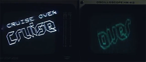
At the Revision 2013 demoparty held last weekend, visitors and guests wanting to check out the latest advances in programming old video game consoles got a real treat. [Abyss] took a Playstation 2, connected the composite video out port to a TV and an oscilloscope, and created the first dual display PS2.
From the official video of the demo, the two video signals are generated from a single video out on the PS2. Generating the composite video out is understandably fairly easy, but the second display – an oscilloscope – is driven during the Vblank period in the composite signal. There’s no audio trickery here; video signals are used for video, and audio signals are used for audio.
[Abyss] took first place in the wild demo competition at Revision 2013. Understandably, too, because this is one of the best demos we’ve ever seen. You can check out the official video from [Abyss] after the break, and the wild competition video after the break.
[youtube=http://www.youtube.com/watch?v=er8CoAAmv2A&w=580]
[youtube=http://www.youtube.com/watch?v=A0plO-FsZ3c&w=580#t=2169s]


I spoke to Dexter at the party – he said it was just a standard video signal, so no trickery involved with blanking periods or anything else.
I’m pretty sure I’ve figured it out now (and assuming I’m right, it really is amazingly simple once you stop trying to think of complicated ways to achieve this result), but I won’t share details as I think part of what he wanted to achieve was to get people to figure this out for themselves…
Split out R,G,and B. drive different displays. Simple as pie and has been done for decades.
so this could be used to drive three displays?
Also, if it was just rgb, it would be easy as pie to drive multiple standard tvs. No need for an oscilloscope.
It’s a single black and white signal over the composite lead, attached directly to both monitor and scope. No external circuitry and no RGB or chroma tricks.
I would suppose, say, rig Red up to the ‘scope’s X input, and Green up to Y. Then essentially by drawing different shades of yellow, you can have the scope’s inputs be anything, and therefore put the beam anywhere.
The speed you draw on the scope at, would affect how much of the screen would need to be yellow.
Actually I see it used composite. In that case, use the chroma and luma signals to drive X and Y and proceed appropriately.
Though of course you could use artistic and algorithmic methods to make the whole thing a bit cleverer, and look nicer. But that’s the simple way I’d do it.
Any good? Close to the answer?
He’s definitely using composite, but if he were using RGB, then the green lead would be connected to the TV, while the red and blue would drive the XY display. The PS2 outputs sync only on green.
Turn on interlacing and split alternate lines?
Something like some sort of filter to switch which device it outputs to based on the field pulse?
So now the question is how long before SONY sues Brian over this.
interesting ideas guys, but no. ralf may be right..
dano/padua – the man behind the gfx.
and now keep on guessing. :) we’re still smiling over here. :)
If you watch the o-scope carefully you can see it’s being used as a vector display. I would theorize that the normal screen is getting a “normal” ntsc composite signal. During v-blank, he’s drawing ONE vector line onto the o-scope. That’s 50 vector lines per second, plenty to achieve his visuals.
I might sound like an Idiot but the PS2 has both Composite and RGB output, are both outputs tied together or can each be used for separate video output? I know nothing of how that end of a PS2 works…
I bet it is just a single signal, no filters, no nothing, just a cable going directly to oscilloscope. Notice the vertical artifacts and you might figure out how it works.. :)
hmm…okay, only one signal means, x-axis is driven from oscilloscope…..thats the reason why they use 2 oscilloscopes….with different time-settings !
and then all to do is to set the average voltage for any line to display on pixel on the right place. next screen refresh you paint another pixel in the same vertical line….the eye is seing so more than one pixel per vertical line.
and you can change the signal fast enough to paint a vertical line….if you are really really fast, you can paint intermittend vertical lines
My guess is that it’s just playing using different output frequencies. Remember with old analog TVs you had to tune it to pick up the picture on a specific channel? Just make sure the signal for the TV operates at a different frequency for those used by the oscilloscope screen. Am I close to correct?
I’d guess that they’re running the scope output using the black background of the composite signal, which is actually dark greyscale data which is hidden by adjusting the brightness of the CRT output so that it clips to black. The scope is then adjusted so that the signals that are visible on the CRT are off-scale high, effectively hiding them, and the lower-intensity background data becomes the scope signal.
This comment on the pouet.net page for this demo is interesting too:
http://pouet.net/prod.php?which=61225#c643691
For those who aren’t aware, some oscilloscopes have *very interesting* video troubleshooting modes. Never had cause to play with them on the ones I have access to, but that might change…
Here we go: http://www.youtube.com/watch?v=NCbb86jphn4
That shows the composite display side-by-side with the oscilloscope display, and everything becomes clear. The scope is configured to trigger off the hsync pulse and scaled appropriately. Once that’s done, any pixel on the screen will show up on the scope, with X position controlling X position, and brightness controlling the Y position (dark grey at the top of the scope and white at the bottom.)