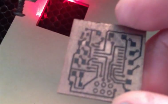
[Rich Olson] wrote in to share his technique for making dual-sided printed circuit boards using a laser cutter. Unfortunately this still depends on etching copper clad boards with chemicals. But his process makes it really easy to produce well-defined and precisely aligned etch resist on both sides of the board all at once.
This can be really tough to do with the toner transfer method. The most common way would be to use a light box to align the two printouts of resist, taping them together before putting the copper clad in between and sending the whole thing though a laminator. [Rich] uses a scrap of acrylic to ensure alignment. He tapes it to the bed of his Epilog laser cutter and cuts the board outline out (that’s the void you see in the image). He removes the scrap and uses it as a stencil for cutting out the copper clad. After prepping the board he coats both sides and sends it through the laser cutter to burn away the paint where he wants to remove copper. Don’t miss his video embedded after the break.
The acrylic outline trick is similar to the laser cutter fence we heard about several weeks back.


It should be possible to make some sort of jig which holds the circuit board in place and which locates on a couple of dowel pins on the cutter’ bed. You could flip the jig over and relocate it on the same pins, keeping precise alignment. Once you figured out the relative position of each side when it’s flipped (e.g. – bit of bare circuit board with some drill holes in it and a webcam + crosshairs on the laser head), you could then simply flip the jig over to laser both sides.
I’ve often thought of trying this, but unfortunately my laser cutter has slightly skew axes (they’re about 89.7 degrees instead of 90) which I normally correct for in the drawing, but which cause a lot of problems when flipping stuff over.
For double-sided photo exposure I made this jig – http://imajeenyus.com/electronics/20110224_double_sided_exposure/index.shtml
which uses the same sort of principle – glass plates with locating pins.
If the bed is not moving, you don’t even need to hold the PCB for it to stay at place. A simple straight corner at known coordinates should be enough. Push the PCB against it, burn one side, flip it and push back against corner, burn other side.
I think this method is probably helpful for those who do not have known coordinates for locations on the bed. I have a laser cutter very similar to this one, and I can tell you that if you move the bed up or down to change the focus then you’ll lose your X,Y coordinate accuracy.
IMO, if you use your laser for more than just making PCBs it’s probably a good idea to make this little temorary jig, especially since if you cut a lot of other things like wood or acrylic you’ll have scraps laying around all the time, so it’s not a big deal.
For a laser which doesn’t have a red dot sight or accurate coordinates (i.e. table lift axis isn’t quite perpendicular to the XY axes), then the best (only?) way of alignment is to cut a reference corner and push the workpiece into it. E.g. I did lots of little round wooden boxes once – cut a “V” shape in a piece of acrylic which is sitting up off the bed (by the height of the wooden box) and then sit the box into the V for engraving.
heard of this method before
it’s potentially bad for your laser if the copper reflects though
if i had a laser cutter i wouldn’t risk breaking it over a pcb
That’s exactly what I was thinking. There are plenty of other good ways to make a PCB. Save the laser for solder stencils.
I don’t think this is really an issue. It’s not like you’re shining the beam onto a perfectly flat specular reflecting surface that will direct the beam right back along the same path and back into the laser tube, increasing the power in the cavity. Copper PCB stock, although it looks kinda shiny, really isn’t that specular (it’s slightly lumpy on the surface, as it shows a slight imprint of the fibreglass weave pattern). You could give the entire board a quick dip in etchant first to matt it (actually, I do this anyway with toner transfer as it helps the adhesion) and reduce reflection.
If you’re worried about the beam being reflected and possibly burning/melting other bits around the laser cutter – rather unlikely. The reflected beam will be pretty diffuse. If you used an air assist nozzle, then a large fraction of any reflected light would strike the end of the nozzle and protect everything else from damage.
Reflecting light back into laser cavities does have detrimental effects since you are effectively increasing the gain of the cavity, so the intracavity power will increase dramatically. I once worked with a 5W argon-ion laser and found that accurately reflecting the beam back caused the output power to double to 10W!
I should add – this argument probably only applies to low (<100W) lasers. On high-power industrial lasers (kW) they DO go to a lot of trouble to prevent back reflection from happening, with lots of fancy polarisers, quarter-wave plates and the like.
You may well be right. I still don’t think I’ll risk it though.
Hi – it’s Rich (the project’s author)
so – I can confirm that trying to cut bare copper in a laser cutter can result in enough reflected IR to melt stuff (like cooling tubing). Would be surprised if it could directly harmed the lens / laser.
I’ve never seen any problems etching off the paint though. The paint absorbs some of the energy – and the power level is set much lower.
Proceed at your own risk of course…
I wonder if you could also burn out the fiberglass for the holes after etching.
Rich here (project author).
I have generally not had any luck getting my laser to go through fiberglass.. this trick might work with a circuit board made from a different composite (forget what they’re called – but they are available – think they use them when milling boards).
also – the binder used in fiberglass can produce some kind of nasty fumes when trying to cut it.
“SRBP” – synthetic resin bonded paper? It’s the really cheap stuff which is much easier to drill than fibreglass. I’d guess that since it’s paper you’re going to get a pretty charred finish, along with whatever resin is in it burning off.
I tried fiberglass once before and it made a real mess ;-)
Generally the only plastics which can be lasered are acrylic/PMMA, polystyrene, and to some extent delrin/acetal. As long as the polymer either decomposes cleanly into vapour or boils off without charring, you can cut it.
I’m always interested to see how people are making PCBs. Have used the toner-transfer method previously, and was impressed with how well it worked – though Ferric Chloride was a bit nasty. Was very happy to discover the hardware store muriatic acid + hydrogen peroxide etching technique, as well as to learn that the ink in sharpie markers works quite well as a resist — great for very simple one-off projects.
The best option I’ve found so far is to use an UV-sheet for etching. If you want solder mask you’ll need an UV-box and UV-sheets so why not use it for etching too? It’s also a lot more reliable than toner-transfer and they use it in the industry.
I went with UV solder masks and have gone on to try photoresist for etching. Whilst I’ve started getting some good results, I found that my UV exposure unit was much too strong for the photoresist. Standard fluorescent strip lighting worked much better. (Obviously this may depend on the board and UV unit you use.)
I’ve often wondered. Could Lasers be used for photo resist boards? It would be pretty interesting
I seem to remember someone trying with a laser diode (from a blu-ray player perhaps?) but it was a bit underpowered and didn’t work very well. Most common CO2 lasers are IR and board need UV.
Also just printing on whatever printer you have to hand and then UV exposing works so well there doesn’t seem too much point – other than the fact that it’s just fun to hack of course.