[Reinis] has a Volvo S80. One of the dashboard features it includes is a 6.5″ LCD screen which periscopes up to use as a navigation system. The problem is that Volvo stopped making maps for it around five years ago and there are no maps at all for Latvia where he lives. So it’s worthless… to you’re average driver. But [Reinis] is fixing it on his own by replacing the system with a Raspberry Pi.
That link leads to his project overview page. But he’s already posted follow-ups on hardware design and initial testing. He’s basing the design around a Raspberry Pi board, but that doesn’t have all the hardware it needs to communicate with the car’s systems. For this he designed his own shield that uses an ATmega328 along with a CAN controller and CAN transceiver. The latter two chips patch into the CAN bus on the car’s On Board Diagnostic system. We didn’t see much about the wiring, but the overview post mentions that the screen takes RGB or Composite inputs so he must be running a composite video cable from the trunk to the dashboard.


I wonder if someone will figure out the DVD formats – the screen and wheel controls are brilliant. It’d be awesome if newer DVDs could be made using OSM data, as millions of cars with the system would get current maps.
My car uses an SD card, that seems to have some sort of additional non-standard circular pads on the bottom face of the card.
My guess is these things use some sort of encryption, and mine has some extra shenanigans involved as well. There was some scary-wording when I bought the car that I should never plug the SD card into a computer – I’m suspicious of some sort of tamper-detect mechanism.
When I buy a map update later I’ll be getting a new SD card with it. I plan on abusing the old card when that happens :)
…to your average driver…
Unless he’s calling us average drivers.
Your*
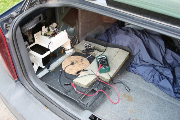
Astounding the amount of space Volvo chose to dedicate to whatever is supposed to be in there. Looks to be over 2 cu ft of space that could have gone to trunk space. With better mounting/routing of stuff they could have gotten by with a lot less waste.
You normally store tire repair tools there
Well, there’s optional sattelite radio and TV unit, CD/MD changer, and a navigation unit which is supposed to go there. Besides, there’s also a fusebox there (and another one in front of the car).
In the last page, I’d guess the street names are illegible because of composite’s bandwidth constraints. (if NTSC, you can’t reliably get a horizontal resolution much above 300 pixels. PAL should be better, but I don’t know by how much)
I was thinking that going RBG might solve the problem. http://www.ebay.com/bhp/hdmi-to-rgb-converter.
more info on the canbus stuff would be nice, a bluetooth retrofit to my car requires a massive amount of work as it was poverty-specced out the factory, so far have retrofitted aux in (pretty straightforward) with a bluetooth dongle and its working fine but next thing is to get the canbus messages for the steering wheel controls so i dont have to have an ugly addition to my dash. Probably just going to butcher a Chinese ELM cable as they have a pic micro and all the supporting hardware present for much cheapness but interested to know how the messages were filtered etc
Well, for starters, I soldered a shield for Arduino using MCP2515/2551 combo. This page has loads of valuable information about the basics of CAN and ICs used: http://modelrail.otenko.com/arduino/arduino-controller-area-network-can
At this point I found out the CAN bitrate Volvo used- it was running at 125kbit/s. Arduino sent the incoming CAN messages to PC via serial port.
Next, I was able to find the relevant message ID’s and data on my laptop, using a custom bash script Basically- I saved all the incoming messages from Arduino in text file for a minute or so, without pressing any buttons.
Then I filtered incoming messages, by ignoring the ones I received when no buttons were pressed. A button press resulted in a single incoming message, and by further filtering the incomming messages by ID I found the data for other button-initiated CAN messages.
Relevant message ID and data format is documented here: https://github.com/festlv/carpc/blob/master/avr-firmware/src/can_volvo/can_volvo.c#L17
Funny thing is- I wrote a GUI app just to filter and find the CAN messages I needed: https://github.com/festlv/canbus_logger (some pics and screenshot: http://www.boot.lv/forums/index.php?/topic/150626-can-bus-loggeris/)
But when I was debugging a problem with some keypresses not being registered, I whipped up a 3 line bash script which did what I needed even better.
I think you might be surprised at the improvement. I would run the HDMI cable to the display and locate the RGB adapter near the display.
Here are some other ideas for you to play with.
Maybe you could use the other data on the canbus to do things like tell you how far you can go on a tank.
With so much spare room have you thought of adding a battery pack so the Pi could stay on for a day or two in low power mode so it could boot up quickly aka not at all.
Use the camera board to provide a backup camera or driving cam.
Add bluetooth so you could stream from your phone.
With Bluetooth you could have your car push it’s location to your phone when it stops. You could then write a find my car app for your phone.
With the GSM connection a remote door lock seems like an interesting idea.
Car alarm/locator.
Install a compass module and accelerometers and gyros “WII MotePlus uses I2C” to make an IMU to augment the GPS. That way you would still have navigation updates for a few minutes or so after GPS drops. The problem with an IMU is the fix will degrade over time but for a short drop like going in a tunnel it should work fine.
I’ve also considered adding accelerometer to detect potholes (which many of our roads have), and warn me the next time I get near them.
Waze alerts are also implemented- not on map, sadly, but they are listed on the screen (when I remember to turn on wifi hotspot in my phone).
If you are on Android you could use Tasker and have it turn on the wifi when your phone sees a bluetooth connection the car. AKA add a bluetooth dongle to you Pi. Or turn on the hotspot when you plug in the charger.
They are still in the middle of the project, but considering they linked to CANBUS project that thy got their source from http://modelrail.otenko.com/arduino/arduino-controller-area-network-can
Denis>> Would that happen to be a Volvo car, that was retrofitted with AUX in?
I myself own a Volvo V50 from ’06, which does not have an AUX in.
Would LOOOOVE to get to be able to listen to netradio from my smartphone!
E60 530d mate, aux in requires coding to be enabled and the stereo has a connector on the back that a cut down pata cable fits, on previous cars iv just built a cable to spoof a cd changer and fed audio in that way, usually plenty of guides floating around if you google your stereo manufacturer :)
You might want to check this out: http://forums.swedespeed.com/showthread.php?105447-HOWTO-AUX-in-for-your-V50-basic-sound-system.
On display connection- it has RGB and composite inputs. Display needs to be tricked into switching to composite input coming from RaspberryPi though. Some details on the serial protocol: https://github.com/festlv/carpc/blob/master/avr-firmware/src/rti/rti.h
I’m using the existing wiring, from original navigation unit to connect RasberryPi to the display.
You can buy an HDMI to VGA converter (I use one of these) for around £10 for the rasperry Pi, but that would mean you would have run additional cabling from the adaptor to the screen, and I am not sure if you would get much of a quality improvement over composite video due to the screens resolution:-
http://www.amazon.co.uk/Adapter-Laptop-Power-Free-Raspberry-support/dp/B0088K7QUQ/ref=sr_1_1?ie=UTF8&qid=1371537906&sr=8-1&keywords=hdmi+to+vga+raspberry+pi
Why not use the RPi to do ISP directly?
I assume you meant SPI. I wanted to be able to turn RaspberryPi on and off automatically. While Raspbery Pi is well know for energy efficiency, in combination with wifi and GPS, it would still drain car’s 70Ah battery in a week or so.
Now, when RPi is off, controller and canbus transceivers would drain the same battery in 100+ days. The efficiency could further be improved by employing sleep modes for Atmega and both of the CAN ICs.
Nice work you have done. I am planning to do something similar on my 2005 V70.
Instead of the Raspberry Pi I would like to use something like that http://liliputing.com/2012/11/rikomagic-introduces-mk802-iiis-now-with-bluetooth-more.html
It has bluetooth support so I could use a bluetooth mouse to operate it instead of the buttons on the wheel. It also has wifi. It has a HDMI connection so I believe I can convert it to RGB plus audio. I am just wondering where I could get information about the pinouts on the original connections of the rti to know where to connect the rgb cables and audio cables. I am a mechanical engineer, so programming is not my strongest side, although I have programmed some atmega boards. But at the first stage I would like to avoid programming if possible and just get my display to show something.