If you’ve got a few solar panels lying around, or even if you want some 120/230 V AC power from a few 12 Volt batteries, you’ll need a power inverter. Sure, you can drop on down to any big box store and pick one of these up, or you can be like [Michael] and build your own (Danish, translation).
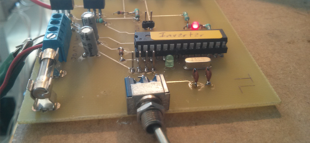
[Michael] found himself in the possession of a few halogen light transformers and decided to make use of them by building a DC to AC power inverter. The inverter is fairly simple – just the transformer, a few MOSFETS, and an ATMega0168 for software control that includes a ‘soft start’ feature that prevents power surges on startup.
The circuit is simple enough to etch at home, although a soldermask and a nice insulated enclosure would probably be ideal for this application.


[insert arduino rant]
j/k
insert microcontroller rant…
http://www.aaroncake.net/circuits/inverter.asp
Two transistors, two diodes, two capacitors, four resistors and a center tap transformer. There’s your friggin inverter.
Nevermind the author of your linked circuit admits that it “can be tricky to get going”. The fact that the recommended tantalum caps cost as much as, or more than a MCU. The tendency of any cheaper substitution to explode due to the high currents required to drive the bipolar transistor bases. Lower efficiency and more heat. And complexity goes way up if you want to add any additional features. How exactly would you propose adding the soft start that [Michael]’s circuit includes, hmm?
Face it, it’s the 21st century. You might as well be ranting that it doesn’t use vacuum tubes. If you prefer to avoid MCUs, a cheap SG3524 or such should do nicely, without being archaic.
I didn’t find it any difficult to get running, and it’s just an example of an astable multivibrator. It can be changed to work with MOSFETs just the same with the addition of two resistors and a bit of re-calculation. No need for tantalum caps then.
I don’t see the point of the soft start feature unless you’re running from a really tiny battery or trying to use a massive transformer (not the case here), so the MCU is little more than a fancy square wave signal generator.
It’s not about the price of the parts, but having a simple, elegant and beautiful solution instead of slapping a microprocessor, or some specialized IC where one isn’t needed. That makes the circuit repairable in the absence of a source for these special parts, like, if your inverter breaks down in the middle of nowhere on your camping trip.
That’s a feature you don’t get with a microcontroller.
You do have a good point about specialized parts. I prefer to avoid them also. If I can do something fairly easily with discretes, and maybe a “jellybean” IC or two like the LM324 or LM339, then that’s what I’ll use. They’re common and useful, plus cheap enough to stock plenty of extras on hand for new projects or repairs.
But I no longer consider MCUs a specialized part. In fact they’re probably the least so. Even cheap MCUs can now replace a huge list of special purpose ICs, and often multiple ones simultaneously. Stocking extras of these is possible as well.
Assuming you’re away from your stash of parts, like in your camping trip scenario, I’m not sure it would be that much easier to find a replacement power NPN than an MCU. Radio Shack maybe, though I find them regularly lacking in basic parts like these. And if there was one nearby, I’d just “rent” an inverter from them, enjoy the camping trip, and return the inverter later. ;)
You can find large transistors from things like car radios, old computers, etc. junk laying about because the specs aren’t that critical. The first time I built the circuit was out of old AT power supplies from a trash heap.
The problem with MCUs is that it’s not enough to have the right part at hand, you also need a compatible computer and a programmer, the right software and the correct program before you can swap the part. Do you know ten years from now that you still have those things readily available?
the transformer inputs should have diodes to clip the kick so it does not damage the mosfets as well
Is that actually necessary in this case? Sure, the body diodes aren’t terribly efficient. But I though external diodes are only required for high-speed switching, to avoid shoot-through in H-bridges and such due to the body diodes’ slow recovery; which certainly isn’t an issue at 60hz.
Since he has the micro in their already, I wonder why he didn’t go for a true sine wave PWM output to drive the MOSFETs?
I’m curious: what exactly does sine wave output get you? AC motors, but otherwise I can’t figure out what would care.
There are a lot of inductive loads out there, and feeding them a square wave is ill-advised. It can end up overheating transformers too. It’s just not a great idea in general.
Not to mention its easier to deal with EMI with sinewave outputs.
Capacitive loads will also drain excessive amounts of current with square waves like that.
With the processing power of the microcontroller on it, why NOT have sinewave outputs?
The AVR isn’t really fast enough, especially not when running the Arduino slowdown software.
Is it really not fast enough to provide sines from an LUT? Or if you’re obsessive you could probably just hardcode the values if you have a constant frequency.
There is no Arduino slowdown software. Arduino code runs “on bare metal” just like when you use a standard AVR environment.
Mostly EMI purposes…also with iron transformers there will probably be audible noise from the harmonics of the square wave…
And it’s been said before, if the MCU is already there, why not utilize it’s full potential? ;-)
Code Red – True sine wave inverters use a transformer that is specifically designed for higher frequencies. This transformer is designed for 50 / 60 Hz and is not suitable for a true sine wave output.
RJ – Fallen – This transformer is normally designed for 12V 4 Amp output, or about 48 Watt (VA). given that the original primary has to provide power for both the output AND the transformer losses then reversing the transform would reduce it’s possible power conversion. To be safe I wouldn’t expect more than 35 Watts in this configuration. Most loads below 35 Watts are not inductive. Loads that require a sine output are normally large loads like fridge compressors.
AnarKIT – AKA – Higher frequencies (EMI) are most often the result of smaller transformers designed for use with Switch Mode Power Supplies that have a lower flux density and higher flux saturation point. This transformer will be coming much closer to flux saturation at much higher flux densities. Flux can’t go from zero to saturation instantly in the same way your car can’t go from 0 to 100 Km/h in zero seconds. So while the input to the transformer may be a square wave, the higher frequencies will be strongly attenuated resulting in an output that is no closer to a square wave than it is to a sine and with minimal EMI.
The limit to potential here is that a 50 / 60 Hz transformer is being reversed. Given the expected loss on the transformers energy transference and the resulting reduction in power expectation, I think this is an excellent circuit using ‘off the shelf’ cheep components.
I don’t understand the answer you give to Code Red: what if we put and LC filter before the trransformer to get rid of the pwm harmoinics and feed an almost clean sine wave to the transformer? I bet this would be better than the current scheme in terms of shape and current waveform going through the panel.
Think about how much power that LC filter would dissapate.
I am really rusty on transformer theory so can someone please correct me were I am wrong.
Problem number 1 with a LC filter is that (if you do the math) you will need a very large non-polar capacitor which defeats the cost implications of this unit as well as taking up a lot of space. This is assuming you use the primary as the L (inductor).
Some transformers have an extra winding that is in parallel with a capacitor which is like an active LC filter.
From memory these transformers are a bifilar wound transformer with flux shunt and a long core.
The flux shunt weakens the magnetic coupling between the primary and secondary so that variations in secondary load current don’t impact as much on the primary. While this might sound like a good idea for an inductive load (which is why you want sine) it achieves the coupling reduction by converting the irregularities to heat. So with an inductive load on this type of transformer it is likely to cook. (overheat).
The reason for the (magnetic) flux shunt is that this transformer has a low turns per volt ratio which means less copper and less cost and of course less efficiency especially at higher frequencies.
So as an answer, yes you could use a LC filter or even drive PWM directly into the transformer but to do so without overheating problems with this type of transformer you load limit would drop to about 5 Watts to perhaps 10 Watts at most. LC filters also have problems with load variations.
It is simply the wrong type of transformer for a sine inverter.
PS: I have seen the more modern halogen light transformers that are actually a Switch Mode Power Supply. They may may be a good starting point for sine inverter.
I wonder what the max. output is. Given that the IRF’s are rated at 14A max, driving 12V which is 168W. At the 220AC side given 168VA, you will not even get one ampere out of it. Is that correct? Or am I missing something? Besides that if you are going to run 14A through PCB traces, the width should be enormous (+- 15mm)? Is it even possible to design a decent inverter, for example 500W or 1000W with this kind of schematic? I think the cost for all the components would be enormous? Although I do like the simplicity of the desing.
If you look at the schematics he is at least using the serial port for programming which means he has a bootloader in there, he is also calling it an Arduino in the description so i guess it is one.
interestingly, the dutch blog post refers to another arduino inverter project (110V) as the base.
http://www.bristolwatch.com/ele/arduino_power_inverter.htm
And if you combine it with the sinewave generator (arduino)….you probably get a cleaner output (aka sinewave vs squarewave):
http://interface.khm.de/index.php/lab/experiments/arduino-dds-sinewave-generator/
This thing works, tryed it on the o scope (was buggy because of the bread board)… note, it outputs in steps not the entire spectrum (at least when I did it) http://www.instructables.com/id/Arduino-Waveform-Generator/
I hope no one tries to connect that to the grid, I was shocked until I realized it was meant for islanded operation. I’d try to do PWM using a timer from the microcontroller (the default 400hz pwm is probably too low) and I believe it would be good to have an inductor in series somewhere to avoid damaging the solar panel too much (LC before the transformer would be a good idea if properly tuned).j
can you please give
information of this inverter as i needed to do my project
this is version 1.1 of this inverter http://techmind.dk/arduino-singleboard/inverter-12-volt-til-230-volt-med-arduino-version-1-1/
Pls I need a PWM 50Hz arduino code for my inverter preoject.
I’m currently experimenting with an Arduino UNO to design a PWM inverter. I’ve written code to produce about 2khz pulses at the output pins (pin12 & pin11). The frequency was chosen for the following reasons.
1) the 16mhz clock on the uno is not high enough to produce higher frequencies given that code snipits use up time.
2) most commercial pure sine wave inverters produce 20Khz to 60Khz but that is not possible with the uno. However, with proper filtering at the output (step-up transformer) the lower frequency I’m using should not be a problem for electronic devices such as TVs, computers and other appliances that use digital circuitry.
3) I plan to use a DC input of 48volts and produce a split 220volts at the output. Common can be connected to ground also.
4) Due to the lower frequency (2Khz) my code divides the 60zhz into pwm pulses at successive 10-degree points along the sinewave. This, of course, produces much more ripple (and harmonics) than commercial units but, as mentioned before, I believe proper filtering will take care of the ripple & harmonics AND the output will actually present a sine wave effect to the load.
5) As mentioned, I use two output pins (12 & 11). Pin12 produces the pwm pulses for the positive halve of the wave while pin11 produces the negative half. This makes it easy to interface the UNO output to drivers for the MOSFETs while allowing dead time between the two.
6) So far I’ve only written code and tested the UNO output with a rinky-dink oscilloscope (xoscope) which all looks good to me. Now I’m in the process of choosing the driver chips and researching how to build the output transformer. I’ve chosen the IRF640N MOSFET for it’s high voltage tolerance (200v) and, if I understand the spec-sheet correctly, the gate switching voltage works at digital levels (5v). This I’ll need to prove to myself. Oh, and cheap.
Correction on my previous post. I use pin11 & pin10 for the PWM while I use pin12 for a 60hz reference square wave which I use for timing and measurements. This 60hz signal may be used to enable/disable the output when needed.