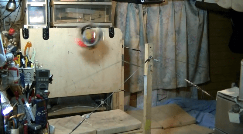
This must have been a coding nightmare, and let’s not even mention the particulars of the mechanical build. The blurred ball near the center of this image is a robot doing a quadruple backflip before sticking the landing.
To the right is a high bar supported by a wood column and some guy-wires. At the beginning of the video below [Hinamitetu] hangs the robot from the bar where it starts its performance without any real motion. The servo motors whine as it gets ready; quickly getting up to speed with full revolutions around the bar. Oh how we wish there was more background info on the hardware! But we’re perfectly happy making our way through [Hinamitetu’s] video collection, which include other gymnastics disciplines like the floor routine. He even posted his own blooper reel that shows the high bar isn’t always a rosy experience.
If you’re thirsting for more amazing performances you won’t be disappointed by this high wire act.
[via Robot Dreams]


Love it, must be such a lot of work to model this in order to write the software.
https://www.youtube.com/watch?v=ckbC0PTfCRE
in this video, you can see the robot executing a cool range of flips, far more interesting than the featured video…
That is seriously impressive! I think it’s funny how every move has a japanese-y name except for one. The Gaylord. Brilliant.
The Gaylord – named after mitch gaylord – 84 olympics IIRC
http://en.wikipedia.org/wiki/Mitch_Gaylord
Tsukuhara and Andrianov(Russian) taught gymnastics in Japan to Olympians
http://en.wikipedia.org/wiki/Nikolai_Andrianov
Still collecting my jaw while writing this. Top notch hack, amazing piece of engineering!
This quy could have made a fortunate crowdsourcing that, am I right :)
I totally flipped when it stuck the landing. Robolympics here you come.
+1
More information on the hardware: http://modthat.com/flipping-robots/
” I used a 2-axis accelerometer located in the head to measure gravity. The measured value varies depending on the robot’s angle of rotation.
The sensors zero when the robot is level on the ground.
[garbled, something about using four distinct sensor regions to detect position and rotation using rise/fall of the sensor information]
Based on these signals, the robot determines when to stretch or bend the leg”
It is really fun to watch, and the mechanical build alone is impressive. Judging from the bloopers reel it looks like the machines are “just” replaying a set of movement patters, with the videos just showing the one time it actually worked out. Also, in one of the videos you can clearly see the soles have industrial-strength sticky pads. Still, quite an achievment identifying and copying the incredibly intricate human movement patterns to a mechanical item.
Well I give him an 11 but I notice the video was number 16, what happened in videos 1-15?
His cat walked across the camera.
I think you mean prototype 16 not video 16 . It looks like this has been a very long project.
Nothing but pure respect to the maker of this awesome robot.
Bravo!
Oh WOW !
That was so entertaining that I almost forgot how much work it must have taken to do this!
The blooper reel was also outstanding!
Wow, that’s impressive! Even with mad coding skills, I didn’t think hobby servo/accelerometer accuracy was quite up to this feat.
Coding – yes, sure, but I thought debugging must ‘ve been a real bitch, given that the robot moves (to say the least) and you would ideally need some sort of wireless bootloader or wireless JTAG ( what was the MCU – I didn’t get that?) else you’ll wipe your connector out with having to re-connect it what must’ve been hundreds of times. I seem to require reloading of the code dozens of times for much simpler projects than this and the ones where the MCU is moving are the worst, takes longest time to upload the new code.
Am I on Reddit?
Cool, i didn’t know that operators of rape dungeons were interested in robotics!
I’ve translated http://www.youtube.com/user/hinamitetu/about . Pasting it below. Apparently he tried to make the first half of this text to sound like machine translation from English. Some people do this because they believe it will improve “reverse” translation from Japanese, only to trouble both human readers and translation engines…
“I used 2-axis accelerometer. It’s inside[robot’s] head. And it will mainly measure the gravity. Its value will reflect rotational angle. —I used measurement at sensor axes will be parallel to the ground as zero-gravity value— I have divided positions in rotations to 4 regions. [Robot] will detect rising and falling signals at border positions(upper, lower, left and right). (Rising/Falling edge detection circuit with zero-gravity value as threshold). I used that signal combined with raw H, L signal(H, L signal with zero-gravity value as threshold) as a trigger. Timings to bend or extend legs will be determined with these signals.”
+Boston Dynamics
Come on, let’s see your Atlas humanoid platform does this. (c:
I was watching each video of the creator and noticed he added a splitting legs.
http://www.youtube.com/watch?v=mT8UIhm0-zE
Bar grab.
http://www.youtube.com/watch?v=k2YnaduNN_M