Self-contained Time-lapse Rig Braves Elements From Thirty Feet

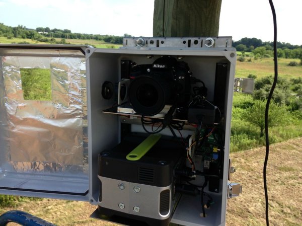
Perspective is a bit hard to grasp in this image, but all of this hardware is mounted thirty feet above the ground. This time-lapse photography box makes use of the sun and a Raspberry Pi to document the goings on. The rig is one of three that were built by [Patty Chuck] to record progress on a seventy acre construction site over the course of eighteen months. The gallery linked above shows off the project well, but a much more in-depth text description is found in his Reddit thread.

What’s not shown in the image is a solar array which powers the box. When they were installed there were no utilities on site. To guard against power-loss there’s a hardware RTC that keeps ticking. The Raspberry Pi uses GPIO pins to switch the Nikon D7100 camera on once every five minutes during the work day. It snaps a photo before powering it down again. It also monitors a temperature sensor and actuates circulation fans if necessary.

He’s planning to post the videos once the project’s done in 18 months. If you see them and remember this post, send us the link and we’ll post the update.

Racing Telemetry On A Cockpit View

ODB

[Martin] has a Lotus Elise and access to a track. Sounds like fun, huh? The only problem is that the dashcam videos he makes are a little bit boring. Sure, they show him flying around the track, but without some sort of data it’s really hard to improve his driving skills. After thinking about it for a while, [Martin] decided he could use his Raspberry Pi and camera module to record videos from the dashboard of his car, and overlay engine data such as RPM, throttle, and speed right on top of the video.

Capturing video is the easy part of this build – [Martin] just connected his Raspi camera module and used the standard raspivid capture utility. Overlaying data on this captured video was a bit harder, though.

[Martin] had previously written about using the Raspi to read OBD-II data into his Raspi. Combine this with a Python script to write subtitles for his movies, and he’s off to the races, with a video and data replay of every move on the track.

The resulting movie and subtitle files can be reencoded to an HD movie. Reencoding a 13 minute HD video took 9 hours on the Raspi. We’d suggest doing this with a more powerful compy, but at least [Martin] has a great solution to fix his slightly uninformative track videos.

2013 Open Hardware Summit Badge Includes EPaper Display

Take a look at this sexy piece for open hardware. It’s what you’ll be wearing around your neck at the Open Hardware Summit this year. WyoLum teamed up with Repaper for the display and Seeed Studios for the boards.

It’s called the BADGEr and it’s both an Arduino and and Arduino shield. There are several different power options; coin-cell, microUSB, unpopulated barrel jack, or the lanyard terminals if you want to wear the power supply around your neck. You can see the five momentary push buttons see above, but on the back you’ll find the microSD card slot along with a power switch for preserving the coin cell.

Check out the video below for a quick look. In addition to acting as your credentials the conference schedule comes preloaded. And of course, this is an Open Source design so you can dig through schematic, board artwork, and code at the page linked above. Oh, and the first hack has already been pulled off. Here’s the badge reading Crime and Punishment.

Speaking of conference badges, DEF CON starts this week. Hackaday writer [Eric Evenchick] will be there and we hope he has a chance to look in on some of the badge hacking at the event.

Continue reading “2013 Open Hardware Summit Badge Includes EPaper Display”

Headless Tethering Between Raspberry Pi And IPhone

rpi-iphone-tethering

This hack doesn’t necessarily have a target application. But there’s a lot of potential. It’s a headless setup for tethering your Raspberry Pi to an iPhone. Building sensor arrays that upload to the Internet (live or just to dump its logs)  immediately comes to mind. But we’re sure there are a ton of other applications just waiting to be thought of.

Tethering is pretty simple with the Raspberry Pi. Just install a few packages that are available in the repositories and make a quick configuration file tweak to allow hot-plugging. But this is dependent on the iPhone being mounted and that task is normally only automatic if the GUI is running. To get by without the X desktop [Dave Controy] walks through the ifuse setup to mount the phone from command line. The result is that your RPi will establish a network connect whenever the iPhone is plugged into it, without any intervention from you.

[Thanks Michael]

Chromecast Bootloader Exploit

chromecast-hack

Well that didn’t take long. The team over at GTVHacker have worked their magic on Chromecast. The HDMI dongle announced by Google last week was so popular they had to cancel their 3-free-months of Netflix perk. We think the thing is worth $35 without it, especially if we end up seeing some awesome hacks from the community.

So far this is just getting your foot in the door by rooting the device. In addition to walking through the exploit the wiki instructions give us a lot more pictures of the internals than we saw from the teardown in yesterday’s links post. There’s an unpopulated pad with seventeen connections on the PCB. You can patch into the serial connections this way, running at a 115200 8n1. But you won’t have terminal access out of the box. The exploit uses a vulnerability in the bootloader to flash a hacked system folder which provides root. After wiping the cache it reboots like normal but now you can access a root shell on port 23.

Continue reading “Chromecast Bootloader Exploit”

Update: Home Security Monitoring Prototype

home-security-monitoring-prototype-update-1

This project is about home security monitoring, but the update is crack for electronics designers. [Simon Ludborzs] continues to work on his prototype and he’s fantastic about sharing his success and failure in a conversational manner.

In April we saw his initial design which combined a SIM900 GSM modem with his own board to let him monitor his home security system without hiring a monthly service. Above you can see a snap of his latest prototype. It’s not fully populated as he’s testing the power supply… which in this state puts out 0V. Obviously that’s not up to his design specification so he started hunting around for the issue. He tells a tale of woe which is near to our hearts. He removed Q6, which is BC807 transistor, in order to test the FET used on the board. This brought it to life and had him looking into the datasheet of the part and its footprint in Altium. The footprint is right, the schematic symbol is wrong. There’s a lucky fix though. Above you can see the original design. The fix was just to rotate the part. This is illustrated as a change in the layout, but it worked with the original pad location. They’re not square to the transistor’s legs but they do still fit the outline.

He goes on to stress test the PSU output and then discuss whether it’s enough for the rest of the project. All in all a fascinating read!

PCBs With Powder Coat

pcb

The toner transfer method of PCB production should be a staple in every maker’s bag of tricks. That being said, it’s a far from ideal solution with a lot of things that can go wrong, ruining hours of work. [Ryan] thinks he has a better solution up his sleeve, still using heat activated toner, but replacing the laser printer with a powder coating gun and a laser engraver.

[Ryan] is using a powder coating gun he picked up from Amazon for about $100. The theory behind it is simple: particles of toner coming out of the gun are statically charged, and bonded to the grounded copper clad board. In real powder coat shops, this coating is baked, resulting in a perfectly hard, mirror-like finish. [Ryan] skipped the baking step and instead through the powder coated board into a laser engraver where the PCB design is melted onto the copper. After that, wash the board off, etch it, and Bob’s your uncle.

What’s really interesting about this method of PCB production is that it doesn’t require a very high power laser. [Ryan] was actually having a problem with the toner burning with his laser engraver, so it might be possible to fab PCBs with a high power handheld laser, or even a Blu Ray laser diode.