Hackaday readers may remember a whistle detection device that I [limpkin] designed some time ago. As [Kevin] saw the new Staff roll call, he discovered this project and wanted to make his version of it.
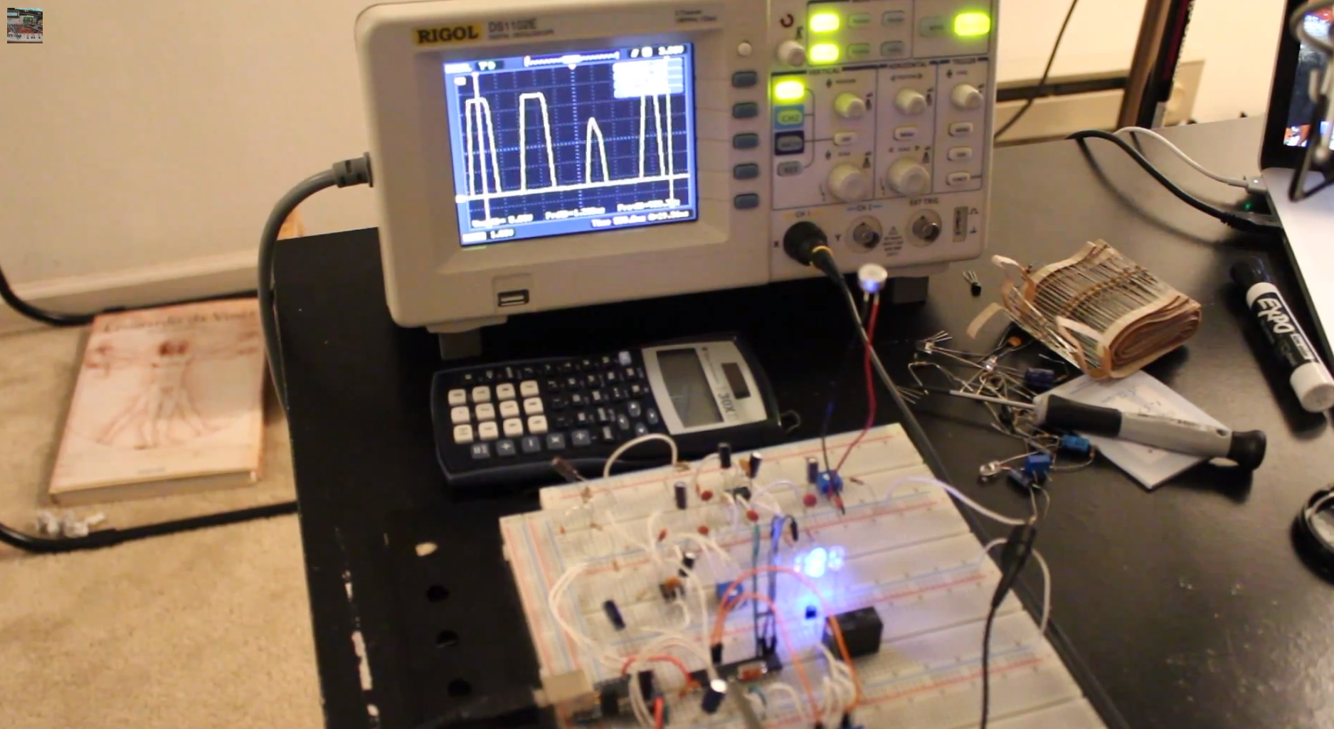
In contrast with the original Whistled where all the signal processing is done in an ARM Cortex m4 microcontroler, [Kevin] uses discrete components, operational amplifiers and an Arduino Uno to detect someone’s whistle. In his video (embedded below), he goes into great lengths to explain how his circuit works along with the theory behind it. In his setup, his microphone’s signal is amplified, passed through a 1KHz-3KHz passive band-pass filter to a non-inverting amplifier with a 1000x gain (!) and finally to a voltage comparator. The Arduino measures the frequency of the signal coming out from the comparator and triggers a relay if the whistle is a ramp-up / ramp-down.
If you want to make the comparison between the two versions of the electronics, here is the link to the original whistled project.


So In what way is this an analog whistle detection device?
You beat me to it… anything that uses a microcontroller ( eg. arduino uno ) is not analogue.
You beat me to it… anything that uses a microcontroller ( eg. arduino uno ) is not analogue.
added:
Maybe the whistle itself is the analogue part. Ramp up/ramp down instead of a ‘digital’ whistle with no variation in frequency…
It isn’t purely analog, it is a more analog approach to the detection of whistles. This in contrast to the original ‘whistled’ project, which sampled the raw audio signal. This ‘analog’ version, contains a more analog front-end. Perhaps analog isn’t the best word for it, but the intent was to distinguish this from the FFT based project. I’m the guy who made the tutorial by the way.
Thanks kevin :)
It demonstrates that you don’t always have to get a big processor and crunch an FFT to dabble in frequency analysis. This method could be done using a very low end micro.
For people who want to dabble in dilter design, look up classic analog filter shematics on the internet and then tweak the filter response with maual calculations or you can use LTspice or QUCS if you don’t like big equations.
I love dilters.
Devices to read about: The Exar XR2211 FSK demodulator or the National Semiconductor LM567 tone decoder.
Indeed, I commented that a while ago, a NE567 or LM567 will do all the stuff and is a classical way to do tone detection, and it’s cheap and doesn’t need a microcontroller.
Microcontrollers are OK though if you use a dirt-cheap attiny or something, but to use a whole board like an arduino for something like this is just silly.
And this video says ‘you NEED an oscilloscope’, seems odd to have a ‘dumb’ version but it requiring an oscilloscope, what?
First read basic theory on what is a phase lock loop.
The error voltage will tell you where the unknown frequency is relative to the known set frquency. The slope of the error voltage will tell you the frequency shift rate.
congratulations on the depth of the explanation, you rarelly get this much detail on the internet. but the code part is really sad – you should at least clean up comments and format it properly before showing it to people. otherwise – nice work!