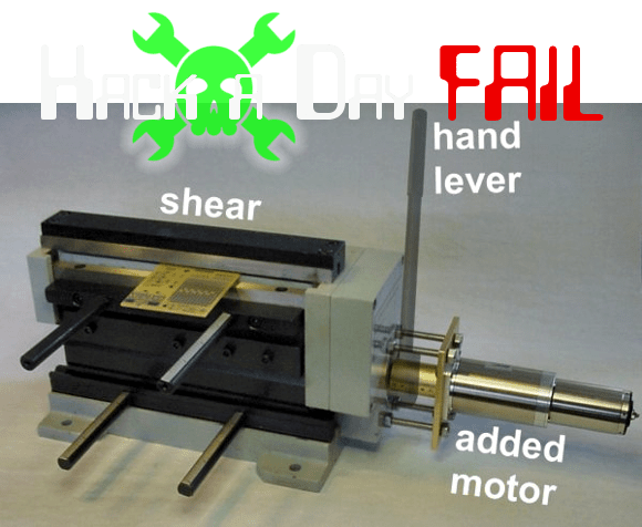
This week’s fail is an attempt to retrofit a PCB cutting shear with a geared motor. The project was undertaken by [David Cook]. Incidentally he’s very near and dear to us as his book Robot Building for Beginners got us started with hacking in the first place.
This $200 shearing tool is hand-operated and can cut through boards up to 1/16″ thick. But [David] really had to crank on the thing to make a cut. This often resulted in crooked board edges. He decided to do the retrofit in order to achieve higher precision. He sourced a high-torque motor from eBay for around $50 delivered.
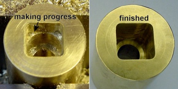
The stock handle interfaces with a square axle coming out of the shear’s gearbox. He figured this would be the easiest way to interface the motor. After removing the gearbox cover he was able to machine in some holes to attach the motor on the outside. This involves some interesting tips, like not using lubricant when machining cast iron, and one technique for machining that square hole he needed to interface with the shear.
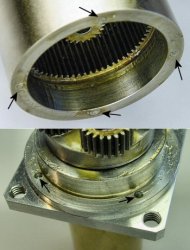
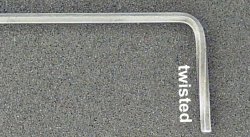
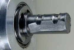
Despite looking so slick the tests with the motor resulted in a total failure. A loud “BAM” was heard and the motor started rotating. All of the screws connecting the motor case to the motor mount had sheared off. He thought his machined parts were okay, but that was not the case. Trying to remove the screws resulted in a twisted hex key. Even worse, the torque of the motor actually twisted its own shaft and the set screws from the coupler dredged deep groove in the steel. That’s a lot of force!
Thanks to [Tomás] for sending in the link to [David’s] fantastic fail write-up.
Fail of the Week is a Hackaday column which runs every Wednesday. Help keep the fun rolling by writing about your past failures and sending us a link to the story — or sending in links to fail write ups you find in your Internet travels.


Next time just put a jack handle or some other thick walled steel tube over the lever to make the pull a little easier :-) Great try with the motor though!
I hate hex keys. I always twist them. And yeah like Nicholas said longer handle will make it much easier to do by hand.
I like your combination of topics, because using a tube over the handle is usually how people end up twisting or breaking hex keys :P
Also i have never twisted a hex key, but i usually use high quality keys that break rather than twist if used with excessive force, normally they just end up destroying the screw head or breaking the thread though, gotta love good tools.
I’ve twisted/broke many a hex key. No tube necessary with those things. I also once twisted the “head” off a bolt once. However, upon inspection of the “break” there didn’t appear to be any twist. There was simply a flat looking mushroom on the top of the bolt still but the bolt head itself simply popped off. It was as if the bolt head itself was pressed onto a “blank” bolt form, if you will. I won’t mention where there bolt came from but I can tell you it’s not a place known for their high quality standards.
Not really sure how you’ve done this other than maybe using cheap tools. I’ve used them countless times on firearm screws which are secured with red and blue loctite. The worst i’ve ever had happen was the screw head would strip. I suppose one time I was trying to remove a stuck torx screw from the IAC motor on a 10+ year old car, with a pair of channel lock pliers around the Craftsman screw driver, and managed to twist the head. But thats the only time ive ever damaged a screw driver
You can remove red loctite easily with some heat. Blue loctite (if applied correctly) should come off just with hand tools. Red loctite is not meant to be removable without heat.
Obviously you’ve never applied enough force then. Looking at the grooves in the motor shaft, I’m guessing the bolts weren’t exactly straight anymore. Possibly not even round.
Last week I had an interesting situation with a surplus t-slot frame I was taking apart (for a later re-purposing of the parts): None of the screws that joined the three-way corner brackets to the ends of the t-slot member could be removed with conventional hand tools!
After some advice from a guy on reddit, I was able to remove one of the hex-head screws using a pneumatic impact tool. Once it came out, I noticed it didn’t have any threadlocker on the threads. I tried the other screws, but the heads stripped out.
I then tried a set of easy-outs, but those stripped the heads as well, not turning them a bit. So, out came a set of nitride drill bits and more effort to remove the screw heads…
Once the heads were popped off, and the t-slot member apart from the bracket, I found that I could easily back out the shaft of the screw with my fingertips – as if they were hand-tight only!
Apparently – due to thermal expansion or something (???) the screws had friction locked themselves in-place. Whether this was by accident or design for this particular t-slot building system (of which I have yet to be able to locate the manufacturer, if they even still exist – none of the several t-slot manufacturers I consulted seem to have my particular extrusion profile) – it was one helluva effective means of keeping those parts together mechanically!
They fix the large wings on wind power windmills on to the base this way. The fan section gets frozen so it contracts a tiny amount, then they slide it onto the base and heat it up. It will expand a tiny little bit which creates to much frictional force that they’re impossible to separate again.
We had one of those shears at work. I think it cost $50 from Harbor Freight. It’s the exact same design, except it’s painted red. We could never get it to work reliably. We ended up throwing it out.
I’ll just point out the having the shear sitting on top of the unit is dumb. It ought to be down low, with a flat table on which your work can rest as it’s sheared.
from Harbor Freight
There’s your problem.
Yeah, but the one in the article is the exact same design, down to the gears. They probably all come from the same factory in China.
Harbor Freight: when you need it to work. Once.
Those PCB shears take a very high amount of torque to operate- would something like a high-ratio pair of spur gears or a worm gear assembly have been a more robust choice?
We used to have a shear in our PCB manufacturing process… it was pneumatically operated… you can get a lot of linear force using a simple pneumatic cylinder, but be careful! fingers shear easier than PCBs…
Pneumatic cylinders are indeed pretty cool and ideal for linear movements, but you need a compressor. Hydraulics would be better for this application
For Hydraulics, you need a hydraulic pump. People are much more likely to have an air compressor than a hydraulic system in their workshops.
Like Nicholas said extend the handle, using leverage will make it much easier to cut.
Probably first he should have calculated the approximate torque needed to shear a board. Since he was attaching to the axle used by the lever, the torque calc should be easy.
If the motor mount screws would not have sheared, I suspect the long mounting screws he made would have torqued next. Would have been better to create a sleeve or neck to mount the motor to the chassis.
Looking at the gears on the side of the shear, it may have been better to install a worm drive motor directly to the primary gear, or mount the motor he selected behind the shear, connected with an idler gear and additional reduction. The additional reduction would also reduce the stress on the motor axle.
Judging from the twist on the shaft, the motor tried to turn it the wrong way. Ultimately, with a smaller sized motor, and configured to turn it the correct way, this may have worked well. Is there a way to control both direction and torque on those motors?
Sure, direction is polarity and torque is current.
Shouldn’t matter which way they turn, the shear is operated by an eccentric.
The motor is way, way too small for this. Should have been a AC worm drive motor, probably 1/6 to 1/4hp.
I’m not so sure about the eccentric…This one doesn’t look like it’s capable of continuous rotation in both directions, so Petiepooo may actually be right.
It does indeed look like you’re right, and I’m guessing this is what destroyed his project.
I can’t imagine doing such work with benchtop tools. Massive forces call for big levers.
Why bother with motors when you have perfectly good leg muscles that can easily generate the required forces?
I’ve only seen this done with tools like this:
http://www.northerntool.com/shop/tools/product_120048_120048?cm_mmc=Google-pla-_-Metal%20Fabrication-_-Sheet%20Metal%20Fabrication-_-143360&ci_src=17588969&ci_sku=143360&gclid=CLaiuPy8o7kCFUmk4AodrTQAxw
THIS:
http://technology.niagarac.on.ca/courses/elnc1236/images/pcbFab/keproSear_sm.jpg
is the gold standard of PCB shears. Sadly, not made any more, but if you ever find one on Ebay, buy it! Kepro 12″ PCB Shear. They used to sell for upwards of $300, but they never sold many. It works like a dream, the cutting blades are replaceable and the leverage is done right.
limit switches?
I’m really enjoying this series. Good stuff Mike!
Crazy ideal why not just attach a linear actuator or air cylinder to the existing handle?
When deep pocket milling like that, instead of going around and around the square lowering your depth each time there is an easier way. Drill your start hole, then set your quill stop about .010″ from the deck you are trying to establish. Now, plunge the endmill in and take .010-.020″ bites out. The finish will be rough, but that’s why the call it roughing. Raise the knee up your last .010 and make a finish pass on the bottom and sides of the hole. Time to mill the pocket will be GREATLY reduced.
Also.. counterbores are not ment to drill holes. That’s one of the reasons there was so much trouble drilling with it.. its not a drill. Some stiff wall tubing will also help reduce the stress on those screws used for standoffs. Or, even better, drill and tap a hole on either side of the new standoffs. Bolt through the casing, and bolt through the adaptor plate. Use standard cap head bolts instead of flatheads, as flatheads have a bad habit of “self centering” where you’re not wanting them to. You can countersink a cap screw, or mill off part of the head if needed. Or, a combination of the two.
Centering up the brass round will be closer if you first indicate the back (solid) jaw of the vise and use that for zero. Add half your diameter to Y, then touch off your X from that point. If you want to dial it down to 0.0001″ (yes, a tenth) you can use a dial test indicator held in the spindle and rotate it around.
Sorry to sound cocky, but manual machine work is what has paid my bills the past couple of years.
When you said “deep pocket milling” i thought you meant spending money on stuff and then breaking it, like pocket mining :P
Another way to do this is with a flywheel and a couple of clutches. One clutch connects the flywheel to a motor to spin it up. The other clutch connects the flywheel to whatever mechanism is needed to slam the guillotine blade through the material to be cut.
Operation is simple with a lever or button that disengages the motor clutch and engages the other clutch until the driven mechanism completes its cycle and disengages the clutch. Let off the lever or button and the motor clutch engages to spin the flywheel back up to speed.
It’s a system that was commonly used on paper shears capable of cutting 500 sheets at once. Some long established print shops still use antique shears of that type because they do the job and they’re never going to wear out.
The big metal cutting shears at my place use the flywheel method. Another try would be with hydraulics. But bolting the shear down and using a longer lever is probably the easiest. Even a simple hand shear or small break will have a ~30″ (12cm) handle on it.
I ain’t no mechanical expert. All I can say is good fail, well worth sharing.
don’t you mean “well worth shearing” ?
Ba-dum tss
For some reason I picture a 2-metre (6 ft) rod with a 5Kg weight on the end. Lift the weight, insert PCB, drop weight and minimal pressure should cut the board.
Of course, not everyone has space for a 2-metre extension rod. I don’t trust moving parts, I’ll stick with electronics thank you.
I don’t think the motor had enough inertia to do it’s job. Once it started slowing, it’s stall torque was achieved and it had to break on the system’s weakest link.
For shearing, at least on a parallel shear, you need a large amount of impulse to do the job. That’s why you see a lot of industrial shears move really fast so they can use the built up momentum.
The gear motor shear method may have worked if it was a cross/scissor shear where constant even pressure was needed to “cut”.
It seems one would also want to mount the motor to it’s own thick steel stand and mount that to the table, not the shear. That would allow the motor to transfer the torque to the shear and not to the bolts.
Problems moving a lever? Here’s a hack: Slide a long pipe on it to increase your leverage. Set the pipe aside when done.
The “longer lever” idea is known as a “cheater-bar” around these parts (no, not that seedy pub where you go looking for your spouse when shes late getting home ;). The fact that the shear has a lever on it should be your first clue that it requires A LOT of force to operate it, making that lever longer to get it working should be your next clue. A strong gear motor may seem like a lot of torque, but a lever will suprise the hell out of you at how much it multiplies rotational force!
“Give me a lever long enough and a fulcrum on which to place it, and I shall move the world.”
-Archimedes
Yeah… i can also deliver more rotational force than my screwdriver. Not sure why that surprised me, but yeah, people deliver a surprising surprisingly large amount of force!
High ratio gearbox for small motor are max output torque limited. He should have read escap datasheets (they probably exist somewhere).
Most are rated a couple of Nm, but the motor itself may put more torque (so it should be current limited).
Keyway, d-shape or Spline. Set screws are not meant for this amount of torque. Power transmission on shafts is a solved engineering problem, I don’t understand why everone insists on doing the COMPLETELY WRONG thing over and over.
This is one of my pet-peves, up there with using the wrong bearings.
If you’re destroying your Alllen wrenches torquing a screw down, then you are USING THE WRONG SIZE SCREW FOR THE APPLICATION
In the event a cheater pipe is need to be use you sre asking the tool to do what it isn’t rated to do. In the event the user isn’t going beyond the stare capacity of the tool and a cheater pipe is still needed the tool was poorly designed. a torque wrench should be used to determine how much torque is require if motorization is attempted again. That way one can search for a motor rated to do the job. One that has has an output shaft that has a keyway machined in it