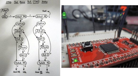
[Pesco] won one of Dangerous Prototypes’ PCB giveaways a few months ago. He opted for a CPLD breakout board. He just needed to put in a parts order and populate the components himself. But then what? He needed a JTAG programmer to work with the chip. Like any good autodidact he choose to make his own rather than buying one. He absorbed the JTAG specification and coded a bit banging programmer using an Arduino.
We’ve used JTAG many times to program ARM chips. But until now we never took the time to figure out how the specification works. If you’ve got an IEEE subscription you can download the whitepaper, but [Pesco] was also able to find one floating around on the interwebs. The flow chart on the left is the cheat sheet he put together based on his readings. From there he wrote the Arduino sketch which implements the programming standard, allowing him to interact with a chip through a minicom terminal window.
[via Dangerous Prototypes]


Saying you’ve programmed ARMs with JTAG is like saying you’ve connected to a website with Ethernet. It’s technically correct, but still highly misleading.
JTAG carries the information, but doesn’t really say anything about what the information is. The JTAG specification doesn’t even deal with programming at all.
+1
the really interesting part of JTAG is the boundary scanning. It allows you to set and read both the inner and outer facing parts of each pin – letting you test both the PCB connectivity and the internal logic
David L. Jones made a nice Video about the topic.
http://www.eevblog.com/2013/07/27/eevblog-499-what-is-jtag-and-boundary-scan/
You’ve got to be joking!
This is a man who is seemingly incapable of recognising a simple full-wave rectifier circuit from his own drawing of it.
His readers are even worse with comments about double coils to increase current handling, “antiparralel Coils to get their current rectifies” and “balanced current waveform in antiphase”.
And you’re suggesting we should trust his word on something far, far more complicated?
(The circuit diagram is at 19:30 – http://www.eevblog.com/2012/05/30/eevblog-284-braun-toothbrush-teardown/)
That was a hilarious video. Thanks for that!
It’s amazing how someone so popular could possibly not understand something so ridiculously basic!
Well… at least he did mention he did not know what that circuit was about.
I enjoy his videos. That’s largely the case because I have not found a better videoblog out there for anyone who enjoys electronics as a hobby. Do you know of anyone else who post similar videos?
Well… Yes…
I suppose it could also be argued that his ‘speculations’ on the matter weren’t entirely incorrect. The coils from both parts of the appliance form a ‘simple’ transformer with a centre-tapped secondary so things like coupling, turns ratio, etc. do matter.
But honestly… Is there really nothing better out there?
umm, what are you trying to achieve here guys? he simply debunks primitive inefficient wireless power transfer, not suitable for EV miracles or so, and also cheap chinese designed product sold as branded miracle, and its not even fruit company miracle in isomething, its cheap as hell, ya … it works but its slow and inefficient – he understants this alll VERY well :-) cheers;
In the first 5 minutes of that video there are so many errors it’s not even worth the time to see the rest.
eurgh JTAG, bane of mine (& colleagues) life. Horrible to debug when things stop working (which state are you in? ScanDR? ScanIR? what is the current IR? hiw many bits have you scanned in? what is the valid value on the TDI and TDO?). I mean, who designs an interface where data is launched on a different edge to which it is sampled?
What I find interesting is what no one is talking about. The original purpose of JTAG is to provide for the built in self test features and functions on boards. The programming of flash devices and of course the CPLD devices as well was a secondary and much later purpose.
By far the most useful article on HAD in over a year and most people are bitching… There’s just not enough such infos out there. But somehow, people were all over the through hole resistor color code thing yesterday, which has been around for decades and brings absolutely nothing new, especially in the day of surface mount parts.
(A follow up) Interesting. He mentions that the IEEE doesn’t want people to read their standards. That’s not quite true. The ones on networking are indeed available. This standard as it happens is only available to members and probably some libraries. But a lucky chap put a copy on Slideshare. It can be downloaded if you’re brave enough to give it some meaningful information.
Oh and his method of blogging does not support comments. So here goes, I wonder if his method will work for walking the JTAG chain? The one that may have surfaced here, that of also using an Arduino, but to program a bricked Wireless router probably won’t.
What do you mean by ‘walking the JTAG chain’?
As he simply provides a set of low level functions, understanding where you are, how long the TAPs are (IR and DR lengths are implementation defined) and how many other TAPs are on the scan chain (if they’re in BYPASS then they’ll add an additional 1-bit to shift through) would have to be managed by the commands you supply to it. So in theory at least there’s nothing you couldn’t do and there’s nothing to stop one from writing some higher-level functions to macro-ise a set of low-level operations to save repeating common sequences (such as ‘R’ to send you to TestLogicReset).
…although saying that, the code doesn’t seem to worry about which state TMS is in when TDI is clocked (I guess it assumes TMS was in the right state from last time) nor the different edges data is launched from vs sampled against so it may not be entirely robust.
In addition to the slideshare version, there’s also a copy of the pdf on-line. Google “filetype:pdf” is your friend.
I did something similar a couple of years ago and explained it in this post: https://eeandcs.blogspot.com/2015/08/jtagxsvf-library-for-arduino.html