[Gerry Sweeney] was tired of messing around with resistors while prototyping his projects, so he decided he wanted a resistor decade box. The problem is they are typically big and rather expensive ($100+). Unhappy with the selection available for purchase, he decided to design his own.
In the accompanying video, he shows off his first attempt after being inspired by a past post we covered that used a combination of resistors and thumbwheel decimal switches. He modified the design a bit and used surface mount resistors instead, which made for a fairly compact and convenient seven decade resistor box. But he still wasn’t happy with it.
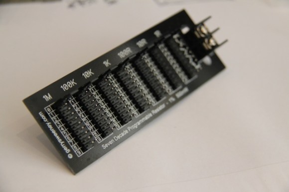
He decided to design his own PCB instead. The simple design utilizes surface mount resistors to conserve space, and jumpers to select the resistance. No bulky switches get in the way and it’s fairly cheap to produce.
Check out the great video explanation of the project after the break. He also shows off the insides of a commercial resistor decade box!
[Thanks Gerry!]


this is like buying a lathe without a quick change gearbox.
A lathe without quick gear change is cheaper and more durable, like his SDPR. He uses jumpers instead of switches that could fail with use.
I wonder if we can make a SDPC (Seven Decade Programmable Capacitor).
Why is it better than a pot?
(it’s not a rude ou sarcastic question)
you can read the exact resistance quickly, and have precise steps of resistance
Pots have very limited ranges, and limited accuracy over that range. You can’t say, grab a 1k pot and accurately set it to 15ohms, and if you want anything over that range, you need a bigger pot. This allows you to set it very accurately using varying decades of resistors, and is a one-size-fits-all solution (in theory)
Maybe I wass to short. Why don’t put N pots, with different value, in series? There’s a precision pot (blue, multi loop) and they are very precise.
I’m not saying that it’s a bad ideia, but for 19 bucks or a very long time of working? I see in eBay that you can buy 15 precision pot kit for USD2.20. If you glue, side by side, 1M + 100k + 10k + 1k + 100R and solder in series, you got a very small 1.111M resistor, “full” precision (you can adjust for an “exact” value). I made one for me.
Hi David, the main idea behind a decade resistor is you can precisely set a specific resistance to a value (within the specified tolerance, 1% in this case) and know that you have that resistance, this is not true for a POT where it would not be so easy to be precise. However, you are right that sometimes a POT would be better, it does depend on what you are doing. The Decade Resistor can be very useful when trying different values without having to disconnect it and measure the resistance you have dialled in, you can instead just look at the jumper positions to know the value.
Gerry
I don’t know many circumstances that require a resistor with unknown value, but 1% tolerance.
@Trui if you have a circuit and you want to find the optimum value for a resistor, for example, tuning a filter or tank circuit, then you can dial up different values until you have your desired performance, and then read off the value from the decades so you know what resistor you should use in your circuit. Decade resistors have been in use in electronics since the invention of resistors, but if you can’t see the use cases for such a tool, you almost certainly don’t need one :) Gerry
I’ve used decade resistors to test linearity of my ADC circuits, but for filter design wouldn’t it be better to just calculate the proper values rather than resort to trial and error on a crummy breadboard ?
If the resistors are only 1% accurate, doesn’t that make every resistor after the first 3 pointless?
They are not pointless if you want a small value and you don’t use the big resistors.
@GERRY SWEENEY. I forget this nice feature (use without power off). But Greenaum said something interesting about the 1% tolerance. I think this tool is very good for “adjacent” resistence values. If you want 1.2k or 73R. For 1001k, the first 1M will be +- 10k and your final resistor wil be 1001k +- 10k, a big flutuation if you are distinguishing 1000k from 1001k. But this last situation is more rare or irrelevant and the tool may fit almost any case.
Thanks for the answer.
@David yes of course, adjacent values are more typical in use but sometimes its useful to trim 1K down by 1 or two ohms.
Trui,
You can (and should) calculate the proper value.
And in theory, theory is the same as practice. In practice, well…
By putting the decade box in place of said resistor, you can quickly and easily tune your circuit to the reality of the situation (did you miscalculate? Were your models not accurate? Are their stray capacitance or reactions you did not account for?). From there, you read your settings, replace it with a real resistor of that value, and continue.
The reason for all 1% values is so that anything you dial in will be 1%. 33.2kohms selected? It is 1%. 162 ohms? Also 1%. Like any tool, you have to understand what it is doing – 133,231 ohms may be the perfect setting for your circuit, but it is meaningless in reality, as your 100k resistor in that set is +/-1000 ohms, and anyway, buying a 133,231 ohm resistor is … I won’t say impossible, but impractical and absurd for most applications are descriptions that come to mind
So yes. You should calculate what you need. These tools are used to allow you to tune real circuits, and your results will be as good as your application.
I suppose if you are debugging a new circuit design, last thing you want is for the pot to spin down to zero ohms, and let the magic blue smoke out.
If I’m so careless to turn all way down the pot with fury, may I be fool enough to select 0R on this proposed tool and let the magic blue smoke out too. There’s no right tool for the reckless.
But toasting the low range brings up an interesting point: Reckless use means cheap useful gear for other people.
I was able to score a Leeds and Northrup 4755 precision decade box at a flea market for $10. It’s a big thing, as in the video above. Serious aluminum chassis, ridiculously high-quality switches. Awesome binding posts. Made in Philadelphia, stamped USAF, crazily high-precision resistors. Last calibrated in 1971, still reads spot-on for the ranges that work according to my meters.
I bought it instantly, as soon as I saw it from the corner of my eye, thinking that the worst that could happen is that it turns out to be completely broken and used up and then I could at least sell it for scrap and still come out ahead. But, lo!
Everything works fine except for the 0.1 Ohm range (that’s 0.1 Ohm +/- some ridiculous number of decimals when it was freshly calibrated), where the resistors are torched.
But that’s OK. I don’t need a 0.1 Ohm range, so that section is getting replaced by a 10k range using some 2- or 3-Watt non-inductive 1% wirewounds.
Which is close enough for my needs. And plenty cheap enough, too. And if I toast the 1-Ohm range, it’ll get switched to higher-power wirewounds as well.
Anyhow, it pays to keep an eye out for abused gear. :)
With a pot, you need an external means of knowing the resistance you’ve set it to. With a resistance box, you set it to a given resistance.
This is true. I made myself a POT-Box and you do set it to the target resistance with a multimeter (a know will give a very approximate value). You can also read the exact resistance after performing your experiment. But a properly built decade resistor box is superior.
Other examples:
http://hackaday.com/2012/08/21/building-a-resistor-substitution-decade-box/
http://hackaday.com/2013/07/14/resistance-decade-box-using-dip-switches/
Your comment is awaiting moderation yet it only links to… this website.
Yeah, some day I dream of a modern comment system for Hackaday. For now we keep a pretty tight leash on moderating submissions to help keep the spam away.
What’s the SNR for this system, if you don’t mind me asking.
how about using multiple MCP4261 digital potentiometers? They’ll cost you $1.5 each, they come in values of 5k,10k,50k & 100k, they can adjust resistance in 256 steps (8-bit). Oh, and there are models with 2x digital pots in a single chip. It’ll give you some accuracy against analog potentiometers, thus can be controlled from uC via SPI.
Digipots are dreadful and full of traps… they typically can’t handle very much current or voltage because there’s a semiconductor in there. The power is severely limited by the size of the actual part, and the voltage across the digipot typically can’t be any higher than the supply voltage of the digipot itself. In practice, the robustness of a digipot, compared to an actual resistor, is basically zip.
They’re good for digitally trimming analog circuits, under very specific conditions, but a decade resistance box needs to behave like an actual resistor, where the main failure mode is “too many watts”. Digipots aren’t too good in that regard.
It’s not much better to use CMOS analog switches for a digitally controlled decade resistance box either – those are just as finicky
i would have loved them to use dip switches …
@BiOzz I avoided using dip switches because cheap ones are unreliable and go wrong and can be intermittent, then you have to de-solder them and mess about to repair them. Jumpers are mechanically simple and reliable devices and when they wear out, they cost 10 cents for 10 more…Gerry
Electronics is not an exact science, thats why 5% or 10% components are the norm need a 108 ohm resistor? a 110 ohm will probably be just fine. Calculations are for those who want to waste a lot of time calculating a value only to find out it doesn’t work that way in the real world. Trui is either an engineer or going to become one some day, a bad one. No practical experience to back up book smarts, which in the end, means squat when every op amp, ADC or 555 timer is different. They will get you in the parking lot of the ball park, but often times not as much as trial and error. Simulations aren’t even close a lot of the time. Prototyping is your friend. That said, there are times, as with some opamp and ADC or calibrated circuits, that require 1% or even better resistance. So I don’t see this as fruitless endevor, pretty useful actually.
I can see why he didn’t use switches. Switches are pretty expensive in the the grand scheme of things and this project would require a lot of them. Also, unless you spring for really pricey ones, switches have contact resistance, which gets worse over time and is slightly different every time you throw the switch. Jumpers are much more rubust and reliable in that respect, are pretty cheap and don’t take up near the space as switches.
Do you need 1% tolerence every time? Nope. Probably not most of the time, but when you do, this would be handy to have around.
Simulations are as close as you want, as long as you are careful to put in all the information. Trial and error with a pot or decade bank is all fine and dandy if you only have one resistor to tune. What if you have 4 resistors, and 4 capacitors ? And what if you can’t tolerate the parasitic capacitance of the breadboard, or the parasitic inductance of the leads to the decade bank ? And if you’ve found the right value, how much does it depend on voltage, temperature other components ? If you say every 555 is different, and you need to make 10000 boards, are you going to tune every single board ? A good engineer needs to be able to calculate/simulate, and know in advance that all 10000 boards are going to fall within the design parameters.
@Trui I obviously use four decade resistor and four decade capacitor boards :). You are right about the parasitic capacitance, and there is inductance to consider too. This is not a perfect tool for every situation but its good for some situations – when you need it, its really very handy. The tempco is rated at 100ppm/degrees C so you need to consider that too just as you do when you “calculate” the perfect value. You see in all my experience calculating ideal values I have not yet found a calculation that gives you results in a preferred value range so you end up taking approximations and building your circuit and in most cases thats often good enough – but when it gets critical, say in setting the response of a RC Tank/RC LP Filter combination, all the calculations in the world for ideal filters will not deal with the source and following impedances and capacitances so well designed circuits will often include a stage of in-prototype tuning to answer that “now I can measure X and see Y, what is the effect if I do Z” questions. Sometimes simulation can work really well but often they do not, using a decade resistor in developing a circuit (or doing trial and error in design phase requires) the engineer to use two very special tools – instinct and experience, and armed with those two things, decade component substitution tools are an enabler.
I guess if you do not see the value in a Decade resistor you almost certainly will never need one in your endeavours.
Alternatives are: (IMHO from best to worse)
a) It would at most take minutes of my time to do it at the design
phase. I usually do all my calculation in Excel. If the requirements
changes, I plug in the new value in my spreadsheet. Done! By the time
it gets to the documentation, I copy/paste that spreadsheet into my
design document.
b) Or the alternative having to walk down to the lab after my proto came
back from the manufacturer, tinker with circuits, then waste more of my
time updating the schematic/BOM to reflect that “tweaked” value for
final production and push that paperwork to the process.
c) If the design is so bad that I have to spent an hour or so to
document the instruction for my contract manufacturer hoe to “tweak”
each pot in a production line.
I don’t know about you, but I usually do thing that requires the least
amount of time/effort. I get to go home early and I meet schedules.
I pick (a) even for my own projects at home.
“I love it when a plan comes together” -John “Hannibal” Smith
^manufacturer *have* to “tweak”.
I agree with @tekkieneet rarely in analog circuitry do ideal calculations turn into a perfect physical manifestation and behaviour. Any design not tweaked in prototype stage by an experienced engineer is not a great design IMHO
I would try to keep the “tweaking” as little as possible and stick to
designing something right the first time. Every step to fix/change a
design further down the process cost more money and time.
That’s the point I was trying to make. Don’t push a design to use a pot
when you could have calculate in a few minutes. Most of my design works
as is from design.
I did run into a situation that my simulation didn’t foresee an issue in
my proto. I spent a few days in the lab understanding the the symptoms.
Took another few day to duplicated it in the simulation after refining
the models. I knew I have something when the model agrees with the real
life results.
From that point, it is a matter of “tweaking” the design in LTSpice. I
can easily 10-20 tweaks in an afternoon and measure a lot of things that
are otherwise not practical or impossible to measure in the lab. After
my simulation worked, I went back to the lab and confirmed the changes
works on my design. I did about 70-80% of that debugging on Spice
instead of the lab. When I have a solution, I know it would work with
margins and not luck with one sample.
need a 108 ohm resistor? a 110 ohm will probably be just fine.
Actually, that’s not how it works. If you buy an x-ohm resistor with a y% tolerance your value isn’t following a normal distribution around x.
When they manufacture them they don’t have a production line for every tolerance. No, they have 1 production line and bin them according to tolerance.
Do the test: take a bunch of 10% and try to find one that falls in a 2% or 1% region. you won’t, they’re sold seperately.
So, whatever series he’s using for his bank: doesn’t matter. He can measure them and have a tolerance as good as his measurement equipment.
This is a very handy tool, I have got 2 of Gerry’s resistors and have used them a few times already. Of course one can use a pot, but it’s not as convenient. You don’t know where you are with a pot until you take it out of the circuit to measure it.
Jumpers are a good idea, when one goes bad just put in a new one. With dip switches you will have to unsolder it to replace it. Still nothing stopping you putting on a header plug with a ribbon cable and wiring it up to a bank of switches.
First I thought the potentiometer idea is genious. But what about 1r to 10r potentiometers? haven’t found them so easily. For instance for usb apps you often need two 63ohm resistor are there pots that can tune into something like 63r (or is it easy to go to 63r with a 100r pot?) If so we could indeed wire some in series and 3d print a nice case for it would make a nice ‘next on my todolist’ project ;). Regarding exactness : you take a multimeter dial the resistance you want and then indeed just plug it into your circuit. It’s not as fast as above solution maybe but it’ll get the job done also I think… The seven decay board is nice however at 18euro a pop think it’s not worth it. Something like a 5er would be more like hey I’ll get a couple of these…
If you know you need two 63 R resistors, why would you even put in a pot rather than just two fixed resistors ?
Walter, you could try those “blue” pots in ebay. search for “”Popular 3296 trimmer”. It’s a pack of 15 values precision pot. One year ago I bought ones like this. I’m with a 100R in hand now to test: it’s change 2,5R in a loop (360º). You can use this pot value to adjust the range 1R ~ 10R. Just a tip.
Hi Walter, thanks for the comment re price. I would agree but they 13 EURO not 18. Unfortunately in low volumes (I am no Farnell) they cost a reasonable amount per unit to make and he pricing reflects that. Lots of people have found them useful and as long as the time saved is worth more than the 13 EURO I suppose you are quids in.
What about NPN transistors replacing the jumpers and a micro-controller to interface with them :) Overkill I know, yet fully automated :)
Probably better to use something like a jfet or relays. The NPN transistor is going to throw a series voltage drop in there that’s going to ruin everything
if you switch the resistors using a transistor, then the voltage differential across the transistor can only go in one direction. Your decade resistance box can now only be biased one way.
If you attempt to introduce any type of digital control to the decade resistance box, your design rapidly increases in complexity, and the range of conditions over which it actually behaves like a resistor rapidly shrink.
The resistor must be passive if it is to be a resistor….:)
Doesn’t programmable hint to there being some more complex electronics than switches in resistors? When I see programmable I at least expect something relating to bit banging,
Certainly not the perfect word but I could think of no other that was better. The resistor can be “programmed” to be a specific value was how I was thinking about it, but as I say that was not a perfect word.
Was this shown on eevblog?
There is a forum post on eevblog and Dave did show one in his mailbag segment a few weeks ago. Gerry
As a side note, boxes and arrays like this do need to be calibrated. When I built one (rotary switch style), my net contact resistance was about 0.4ohms. This is well outside of tolerance for the 1 and 10 ohm range.
The solution was to replace the first 1 ohm resistor with a 0.6ohm resistor, and the first 10 ohm resistor with a 9.53 ohm resistor.
This, btw, is how professional boxes are made (except they trim every setting as needed).
Now pondering box protections: how to keep from popping the box with too much power. Simple thought is to monitor temperature of resistors (probably as clusters) and disconnect if they start to overheat. More complicated would be active power monitoring (current + voltage), with a cutoff if power rating is exceeded.