As connected as we are, reliable and affordable internet is still a luxury in the far reaches. [kohleick’s] country home is not just remote; with temperatures dropping to -30C in the winter, it’s practically Arctic. His solution for controlling the thermostat from afar was to take advantage of the GSM network and implement a SMS-based heater controller. The unit typically operates in “antifreeze mode,” but sending a simple text message prior to visiting causes the heater to kick it up to a more comfortable setting for your arrival. Daily logs report the system’s status, and an alert will trigger when temperatures fall below a set limit, thus indicating potential faults with the heater.
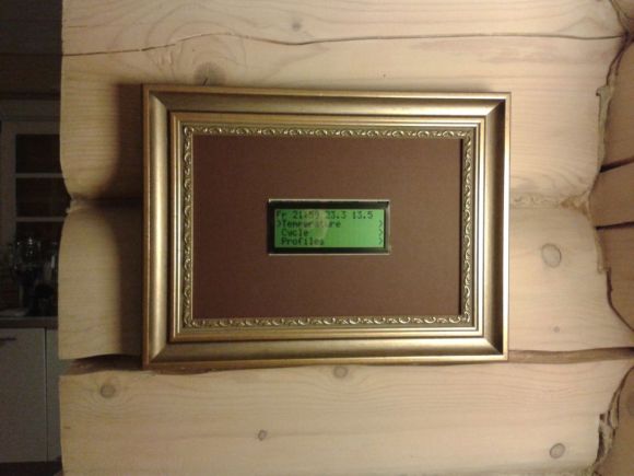
The build uses a Freeduino paired with an external GSM modem for communication and an LCD to display current status and menus, which users access via three buttons on the side of the picture frame. [kohleick] connected two temperature sensors: one directly to the Freeduino’s shield and a second outside the house. After the temperature sensors detect deviance from the set point, or upon SMS instruction, the Freeduino will crank up the heat through a 5V relay attached to the home’s boiler. Head over to the Instructables page linked above for a bill of materials, schematics, and the code. The Siemens GSM modem in this build is nothing to worry about, but be careful if you try to reproduce this project with an Arduino GSM shield, or your house might really heat up.


Must be nice!
I think it is a really cool build but I have some questions and suggestions.
1. I do not see any buttons. Can you adjust it without the phone?
2. Maybe hinge the picture frame so you can put a picture in it to cover the display. The picture frame actually draws attention to the device while not hiding it IMHO.
Maybe add this http://playground.arduino.cc/Main/MQGasSensors so you can use it as a smoke dectector as well.
1) on his page it mentions the buttons.
2) maybe he wants to draw attention to it?
1) I think the buttons are on the side, hidden just behind the frame edge when viewed from the front.
2) Personal preference, but instead of such a large blank matte, I’d add some artwork that the LCD fits into and appears to be a part of. A perhaps altered version of “Composition in Red and Blue” by Piet Mondrian comes to mind as a quick example.
“an LCD to display current status and menus, which users access via three buttons on the side of the picture frame.”
I sincerely try to address all the important points in the body of the article I’ve written to provide a succinct overview so you don’t have to pluck through the source yourself unless you want more specific information, so please read it!
Sorry my bad. I missed that. I did start to read it but scanned right to the parts list to see what other features you might have added. It is a very nice build as I said. Do you plug into a UPS in case of a power failure. I have friends that live in Vermont and they have had ice storms that took out power for days. I know that no power probably means no heat but you might have a chance to go and turn off the water before you have a flood to deal with after the power comes back on.
Useful project.
I haven’t looked too closely at it, but here’s some general advice. Should the Arduino fail for any reason, there is a potential for property damage due to freezing or overheating. So this is one of those cases where I would be very thorough about making it bulletproof.
Especially since there is also an entry point for external and potentially erroneous data – the GSM module. Make sure your code can handle any random data gracefully. Sanity check the value of any “set temperature” command it receives. Make sure there’s no possibility of buffer overruns in your code due to invalid length fields or lack of terminating characters. Don’t assume any supporting libraries you use can also do the same, examine the source and/or test them.
Code defensively. Always use your watchdog timer. Try glitching your MCU with a variety of simulated blackouts/brownouts, add an external reset circuit if your MCU proves or is known to be lacking in that department. Make sure all components run cool and well below rated limits. Think of ways to detect and gracefully handle failures. For example, if it can monitor the actual relay output, and it determines that the relay contacts have fused, it could send you a message. And so on.
Most importantly, be honest with yourself. If you can’t do this with high confidence, add a simpler or off-the-shelf redundant system to absolutely limit temperature excursions.