Some of us may have been accused of living in Mom’s basement – [Benjamin] kicks it up a notch by keeping an industrial robot in his parent’s attic shed loft.
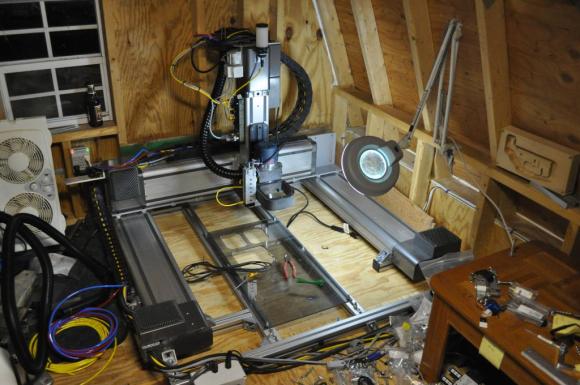
[Benjamin] was tasked with stripping down some retired equipment at work. It turns out the “retired equipment” was three Cartesian robots from Adept Robotics. These are large industrial XYZ platforms capable of high speed movements (3000 IPM rapids!).
Getting from a decommissioned machine to a working CNC is never a simple path. In this case [Ben] was able to make the transition relatively easily. Each axis of the robot has a 400 Watt Yaskawa servo with a 65k encoder and brake. The original Adept servo amps and control system was still working, so he kept it. The controllers were new enough that they communicate over a daisy chained IEEE1394 (Firewire) link. That is relatively modern compared to some of the conversions we’ve seen in the past. The final piece of the puzzle was G-code creation Translating common G-code to a format his machine could recognize. Ben chose MeshCAM for the task.
One problem [Ben] ran into was stuttering on the X-axis. The original machines only had a single sided drive system on the X-axis. Single side is fine for an assembly machine that doesn’t see any tool load. However for a CNC machine that will see spindle loads, a single side drive creates a twisting force which threatens to rack the entire frame. He used one of the drive systems from his spare robot to convert his main machine to a double-sided drive, eliminating the issue.
[Ben’s] eventual goal for the robot is to machine high performance auto parts. We’d be a little worried about a machine like this milling steel. Aluminum extrusion is pretty rigid, but can it hold up to those sorts of milling loads without flexing or tool chatter? We’ll be watching this one to find out.
Update: [Ben] clarified a couple of points in the comments below – and added that he’s “currently seeing repeatable accuracy of about 1/4000th of a millimeter.” Wow!


I just want to clarify a few things: The major issue I had was not creating g-code; any modern CAM processor will do that easily. My problem was taking an industrial robot designed to do one repetitive task perfectly every time, and making it read g-code and translating that data into meaningful motion.
The aluminum extrusion is not permanent, as right now I only have about 2″ of clearance between the bottom of the Z-axis and the extrusion, which Beverly limits it’s range of vertical motion.
This is not in my parents attic. It’s in the shed. lol.
The dual axis is not the Y axis, it is the X-axis.
With my current licenses installed on the controller, and the enhanced kinematics software, I am currently seeing repeatable accuracy of about 1/4000th of a millimeter.
Thanks for the corrections Ben, I’ve updated the post to reflect them. 1/4000th of an
inchmm – you could use that machine to mill printed circuit boards.“… repeatable accuracy of about 1/4000th of a millimeter.” That’s a little finer than 1/4000 of an inch.
About two and a half times finer.
Nope, 25.4 times finer
Hmm, I’m starting to see some possibilities here….
Jørgen Mads Clausen started his company in his parents attic, getting laughed at by the neighbours.
Well today we call that company Danfoss and we are about 23.000 employees :-)
So, keep it up!
When you say “repeatable accuracy”, is that encoder counts translated to linear accuracy, or as measured on a machined piece?
(I should say, it’s impressive for encoder counts, but presumably translates to slightly less accuracy at te other end of the cutting tool. 1/4000mm at the piece is phenomenal. Either way, this is an awesome job.)
Very neat. I often see the industrial automation slide come up but they use their dedicated controllers and that makes them tough to use. Neat to see someone get them working.
Saw it mentioned that you were looking at liquid coolant. I would steer clear of that, look at a micro drop coolant system. It delivers concentrated cutting fluid via air to the cutter and makes much less of a mess. I use it on my cnc mill and lathe. Bijur Spraymist is one model and Trico also makes a micro drop unit. These are not to be confused with the venturi misters, they make a mist that hangs in the air and is no good to breathe.
I will definitely look into this. Thanks for the tip!
I can guarentee you don’t even know how to measure whether a machine repeats to a quarter micron.
true that!!
I was able to borrow a laser interferometer from work.
Yep, that would do it. We have a HP one here at work. Did you measure screw drunkeness while you had it?
@Ryan Turner Ha, take that. :-) You should give people a little credit before jumping in and say they are lying or incapable of something. This is an impressive job, give the guy the credit he is due.
Benjamin, great job! Lucky you to have the second screw drive for the Y axis. I have a similar Cartesian Shibaura robot, but only one drive per axis (it used to be a part of a pick and place machine) – the thing is so cantilevered I’m afraid any considerable lateral force is going to rip the axis apart. I’m hoping to turn mine into a laser cutter – does not create any lateral forces – if I can find any documentation on a Shibaura that it :).
Other than that, these Cartesians make great CNC routers – very accurate positioning, quick like crazy and pretty large.
By the way, how come the color coding of the warning light is reversed? When a machine is moving, it should be yellow (and flashing if you have a flasher) and green when it stopped normally (red if on an error) – it’s for us, people :) – when it’s green, it supposed to mean that you can come up to it, so it should be stopped by then.
I’ll be watching new developments of your project with great interest!
Cheers!
Haha, funny you noticed the light. I usually use those lights on fixed work cells at work as stack lights, so we use red as error, yellow as home-reset required, flashing green as everything normal but production stopped, and green as operating normally.
Is that you Johnny Five?
1/4000 mm = 250 nm. I do not believe it!
9 millionths of an inch, Ha Ha Ha Ha
Looking at some of the variations in the layers on the wood cuts, it’s pretty obvious that the machine is not even close to having a repeatable accuracy of 1/4000th of a millimeter! Also not sure how you would even measure that, and that on wood?
He doesn’t actually say it’s machined accuracy. If you’re a machinist, you can measure at the piece. If you’re building a robot, you start a step or two before that, with the encoders at the servos. If “65k” means what I think it does, then you have 65 thousand pulses per revolution of the encoder. Knowing the gearing, you can translate revolutions to linear movement, and thus pulses to linear movement (we call it a K-constant in my area, and it is literally a multiplier to get theoretical mm of linear movement from encoder pulses). So you start by calibrating your motion control to get the servos stopping “in the same place” each time you send them to the same target. 65 thousand pulses per revolution is pretty fine, and getting the servos to stop with a theoretical accuracy of 1/4000 mm is pretty impressive, I reckon. It’s not the same as machined accuracy, but I don’t think that’s the claim.
Although the more I think about it, the more ridiculously fine 65 thousand ppr sounds, but 1/4000 mm is well out of my league even at the encoder, so who knows.
Correct, I am not talking about machining accuracy. It’s a wood router in a ABS plastic mount for pete’s sake…… 65,535 points of measurement with 10mm/rev ground ballscrews. The controls for the robot are very advanced, The robot is capable of reporting many things back such as torque, moment, inertia of the tool, how well the servo motor is performing using the current DAC settings, etc. The 1/4000th value is a reported value as in theory it could hit 0.0001525mm per pulse.
The variations in the wood were actually not the robot’s fault at all. MeshCAM 5’s 3d Roughing feature caused that to happen. If you watch the video, you can see that the robot almost pauses randomly at various points and that’s because I had feedforward (The controller’s ability to pre-process the next requested movement) disabled, causing Z-axis movements to cause a stutter.
Man, 65k ppr is ridiculous, but I guess that’s what it takes for that finesse. I work with 650ppr stuff, and I’m happy with 2.5mm either way at the piece, but then that’s all I need. I might hit you up for more details when I’ve had a chance to properly read the whole thing, this is the best thing I’ve seen on HaD in … possibly forever. Mind you, starting with the right discards helps ;)
65k is nothing for modern servos. I have some mitsubishi servos with 131,072 line encoders and new mitsubishi motors have 4 million count encoders (22bit absolute).
It is not that the motor can move in 1/40000000 increments, it is that it is smoother at slow speeds, you have more control over the motor. It also lends itself to better electronic gearing if you are using that.
Exactly. The higher resolution means your accel/deccel profiles will perform better. I think of it as allowing the predictive kinematics algorithms to have a better idea on how the servo will react. Of course that also comes down to how well you can control DAC’s on the amplifier. I have a few mitsubishi cabinet mounted amplifiers, but the level of control they offer is nothing compared to what the Adept CX controller can do over firewire. When I first started working with these robots about two months ago, the controllers were still using software from 2003. Command line, and difficult to figure out to setup. Now that I upgraded to the new firmware, and installed Adept ACE (Available free to download and run emulated robots and controllers: http://www.adept.com/index.php?option=com_content&view=article&id=367&Itemid=484&dir=JSROOT%2FDownload-Library%2FSoftware/Adept-ACE) and the sheer versatility of the system is phenomenal.
… still think it’s a great project though…
awwwwwwwwww man, how come all these other guys get the wicked stuff :/
XOIIO, I’m normally not a jealous person, and I consider myself luckier than I deserve, but!….. What company gives away $100k worth of “retired” equipment, and where can I apply for a job there?!?!? :-)
Sadly, I was told to throw them away. Each robot was about $55K USD when we bought them back in 2003, and they paid for themselves in the first several months of production. It was cheaper to pay me take a few parts off the machines and throw them out than to re-use them in a new design. The robot I am currently using screwed in something like 28,000,000 screws (8 per unit) in its 8 years of production.
It’s usually a case of knowing the right people, and having storage space. I know some people who do know the right people, and they have 3 industrial robots (big orange arms). The only thing they had to do was removing them from the factory floor.
Giving them away was cheaper then paying someone to remove them.
And a few months ago they got a full decommissioned greenhouse. These people collect just about anything :-)
“Getting from a decommissioned machine to a working CNC is never a simple path.”
I say, “Getting a decommissioned machine… is never a simple path.” B^)
“spare robot”. Can I have it???
Turn a decommissioned robot into a CNC machine??? Why didn’t I think of that? – down to the robot recycle depot I go tomorrow… oh wait…
Is that a wooden ar-15 lower on the right?
That caught my eye too
Indeed it is. I’ve been running a lot of different types of parts to find out where my code fails to properly interpret g-code. Half the mag was accidentally milled away and there is a large slot in the other half of the mag from when my code decided to ignore changes in the Z-axis.
High Speed Machining (HSM) tool paths would help a machine like this greatly. WIth the rapids this machine can achieve the and the less than rigid spindle mount HSM paths would help keep tool load down, result in quicker cycle times and better final parts.
CNC Cookbooks G-Wizard Calculator is also a good resource, it will help you get your feeds and speeds in the correct window so your not putting extra heat in the tool.
wonderful
He certainly got a great score from his job and did something amazing with it. I am still chuckling as I used to live in my parents’ basement and tinkered endlessly. Fortunately, it turned into a future career.
It makes sense that a single side drive would create a twisting form, which could be resolved by adding a double-sided drive. My husband wants to transition a decommissioned machine into a CNC, but still needs some spindles and other parts. Hopefully he can find some online that are high quality. He’ll have to keep the double-sided drive tip in mind!