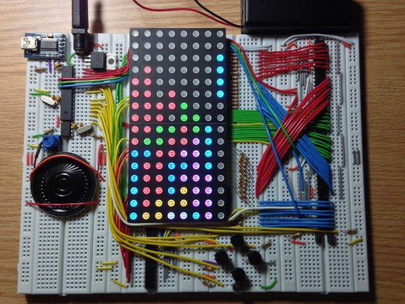
Look closely at the colored pixels on this pair of 8×8 RGB LED modules and you’ll be able to pick out some of the familiar shapes of Tetris pieces. It’s impressive that [Jianan Li] built his own color Tetris including the theme music, but look at this breadboard! The layout of his circuit is as equally impressive as the code he wrote to get the game up and running. It takes a fair amount of planning to get a circuit of this complexity to fit in the space he used, right?
There are two microcontrollers at work, each running the Arduino bootloader. The main chip is an ATmega328 which is responsible for monitoring the buttons and controlling game play. The other is an ATmega85. The eight pin chip listens to it’s bigger brother, playing the theme song when the game starts, and pausing or resuming to match the user input So is the next stop for this project playing Tetris on the side of a building?
Don’t miss the demo video after the break. We’ve also rolled in a video of his Arduino-based piano. It’s built on a breadboard that’s nearly as impressive as this. But what delights us is his skill at playing Pokemon themes on the two-octave tactile switch keyboard. Obviously those piano lessons his parents shelled out for really paid off!


Cool project and definitely a piece of art ;)
The µC for the sound is an ATtiny85 not an ATmega btw^^
Pieces of art indeed. :-)
s/ATmega85/ATtiny85
These are awesome. I’ll never feel guilty about just breadboarding something again. We should have a contest for the most artistic breadboard that actually does something significant and everything is needed for the circuit.
>It takes a fair amount of planning to get a circuit of this complexity to fit in the space he used, right?
No. Not really. There’s a lot of wasted space on the leftmost breadboard, and a little on the rightmost, but they way it is laid out makes a lot of sense. I don’t think it could be done on one less breadboard without everything being incredibly packed in there. Not that this isn’t an impressive project or anything, but it doesn’t take a whole lot of planning. I’d bet [jianan] spent 5 minutes or less thinking about high level breadboard layout, and the details were filled in as he went.
My buddy Mike has some stunning wire art. I wish I could post them up here some how.
Very nice. I’m messing around with LED arrays and need to get these.
Why are the bundles of red and blue wires crossed, instead of going straight ?
Before I started to do the wiring, I planned to dedicate the top two shift registers to red, middle two to green, and the bottom two to blue so that it’s more intuitive and would be easier to debug. But you just made me realize that I could and should just let those two bundles of wires go straight to the right, and just chain the first and fifth, and the second and sixth registers together. Thanks!
Or just swap the bits in software.
Thanks for the clean code. Just ported it to Wise Clock 4:
http://timewitharduino.blogspot.ca/2013/09/play-tetris-on-wise-clock-4.html
My pleasure. I tried really hard to make the code independent of the size of the display, but there are still a few places where I referred to the actual display size (8, 16…). I got to clean up my code some time today.
Hey bro im working on this project and would love to hear a bit about your work. my email is valentin90918@yahoo.com
thanks-