[themonkeybars] recently uploaded a time-lapse video of his DIY synthesizer build. First off the video itself is a pretty neat hack. An iPhone time-lapse app was used to capture one frame every 5 seconds. By the time the build was complete, approximately 46,000 frames had been snapped. This boiled down to over 43 minutes of youtube footage. [themonkeybars] didn’t work full time on the project, so the video covers about a year’s worth of work which we think makes it even cooler. The synth is also featured in much of the video’s soundtrack.
The synthesizer itself would be classified as an analog modular synth, a type we’ve seen before. Modular synthesizers are one of the earlier forms of electronic music. The synthesizer is composed of discrete modules such as oscillators, modulators, and filters. The modules may be housed in the same box, but they are not internally connected. All connections are made via front panel patch cables. This is where the term “Patch” came from.
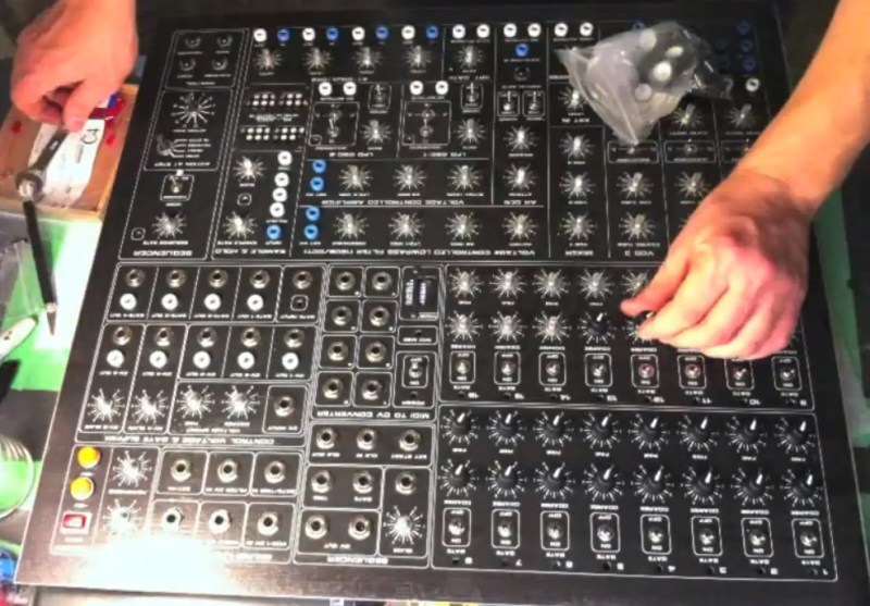
As you can probably imagine, all these cables, switches, and dials make for quite a bit of metal work in the building of the synthesizer front panel, and even more wiring. [themonkeybars] takes us through every step of that journey, from the bare metal front panel to the finished instrument. Much of the internals are based upon Music From Outer Space kits, with the Sound Lab ULTIMATE kit forming the heart of the project.
We really enjoyed his novel tilt mount for the printed circuit boards. The tilt mount allows both sides of the PCB and nearly all of the front panel to be accessed for modifications or repairs. Some of the other interesting features include a lucite window on the bottom of the case, and red LED strip on the inside. The red LEDs create a dull glow that can be seen through the patch connectors, yet doesn’t overpower the panel mounted indicators. All in all this is a beautiful build!
[Thanks JohnS_AZ]


Did telephone operators patching through calls predate the invention of synthesizers? Perhaps no one thought to call it patching at the time.
I believe the writer meant the origin of the term “patch” to refer to a sound clip.
I believe the writer may have meant the use of the word ‘patch’ to refer to a sequence of sounds.
http://en.wikipedia.org/wiki/Synthesizer#Patch
Yup – this is what I meant. I’m dating myself, but some of my first synth sounds are recorded on patch sheets…
Random House identifies the telephone patch-cord as originating around 1925-1930, but I can’t find a specific usage citation. That coincides with the explosive growth of the telephone system, and it makes sense that industry jargon would’ve entered the popular lexicon around that time.
However, I had always personally been under the impression that a “sound patch” as a sequence of sounds, originated with cutting and splicing audio tape (patching something together) on an editing desk. Both processes (patch cords, and tape splicing) would’ve been commonplace in a studio and the terms may have blurred, as well.
Yes. The telephone predates pretty all active electronic components, with the exception of the odd wierd electro-chemical-mechanical thing that might have tortured electrons before the thermionic valve was invented. So that means it precedes electronic synths.
These were called patch-bays in all sorts of things that used them, originally telephone exchange stuff, but other stuff too. When the first modular synths needed a system to tie themselves together in a versatile way, this was the obvious thing to do.
Basically it’s a lot of modules, voltage to frequency, frequency to voltage, oscillators, low frequency oscillators, controllable filters and gates, and more. You wire the modules up to each other and see what wierd sounds you get. The keyboard would produce a control voltage, which would usually be connected to control an oscillator. That gave you the basic notes. Then the wires and optionally more controllers and switches connected the other bits and gave whatever sound you were after, from violins and pianos to wierd spacey things.
I think it was a bit of musical knowledge, a bit of electronics, specific knowledge of the stuff involved, and a lot of experiment and play that got the use from these. You can see film of early 80s and some 70s bands playing stuff like this in the studio, often with at least one oscilloscope.
The “patches” second use came later. When computerised synths started doing a lot of this in software. A “patch” was a group of settings, a “voice” for the synth. IE a guitar-sounding patch, etc. You loaded it into your computer synth program, and the patch file instructed the software synth what to do. Each patch is an instrument. Though they were still sets of parameters and processes, not samples.
Well, usually. It’s more versatile than that, you can have patches for other stuff too. But when MIDI-types in the 80s and 90s talked about trading patches, that’s what they were. Software settings and instructions that performed the purpose of actual wired patch bays of old.
In the last few years CPU power’s come along enough that modern computer synth software has gone all the way round the clock. Now the separate analogue modules are back! Only this time, emulated. Same as the control voltages and frequencies of before, but now they’re numbers. You can often load in presets, versions of particular old amps, with a graphical picture of the old bay full of holes. Click and drag virtual cables between them, and billions of transistors and MIPS faithfully calculate the few dozen op-amps and transistors of the old days!
That last bit, I meant “versions of particular old synths”. Not amps. You get a photo of the synth with representations of it’s controls and patch bay to twiddle with. Gives the old-skool sound, and a productive and interesting way for musicians to create new noises. Also saves you paying many thousands for the few old real analogue synths that are still functioning.
That’s an amazing piece of work and a great sounding synth too.
Yea, really nice sounds.
If anybody can sit through 43 minutes of this please leave a comment and tell us what you think.
I got through the first 2 minutes and then jumped around a bit. This guy clearly knows what he is doing.
Wow, quite the build. That’s a lot of soldering PC boards. And point to point wiring. I see he had some drawings but did that come as part of the kits or did he figure all that wiring out all ahead of time. I suspect lots of planing involved there and in laying out the front panel and how did he get the self-stick decal for it. That’s always the biggest challenge making any project look really sharp or “professional”. This one’s got it, sounds good too. Nice use of the Dremel there in several spots.
Reminds me of building a Heathkit TV. oops dated myself on that one.
I asked him about the overlay in the video comments. He had two copies of it printed on a large format printer, on the heaviest paper stock the thing would take. One to use as a drill guide, and the other as the final piece (pretty smart). It looks to me like he used contact adhesive to stick it to the panel, then coated it with something.
I saw it being coated in some sort of varnish, He might have been better off using printed vinyl from a signage shop in the area. Suppose the test of time will tell if it was a bad material choice.
After a few minutes the music reminded me of a cheap 1980’s porno flick.
why do i desperately need to pee everytime i watch stuff like that
I’m confused on one thing. He didn’t modularize the build to allow for the use of connectors inside for easy removal and repair of the system. I know these systems are very sensitive to any change in cable length, etc, so perhaps that was his reasoning.
Mind you, that’s way better than I could do it, and he obviously has time to enjoy his hobby….I remember time…
I think the PCBs don’t have modular connectors because it looks like he used a lot of Ray Wilson’s MFOS synth boards and those were designed without modular connectors.
Trying to watch the whole thing but work keeps getting in the way.. >_>
Awesome build, two questions though:
1. What is the purpose of the LED array?
2. (Knowing that it is often not about saving money…) How much did this cost and how much does an equivalent commercial product run?
LED array: no clue.
As for cost, I can say that I’ve started building a simpler analog synth with 6 basic modules. I have the power supply, 6 PCBs, all the components, aluminum for the panels, and I’d say I’m into it about $450 so far (and have a ways to go). I would -guess- his build cost has to be around $1,200. And buying one? I’m not certain that you can.
“And buying one? I’m not certain that you can.”
And why would anyone want to? A digital synth can do about a bazillion more things, do them better, do them faster, and for less money. Even a software module synth is cheaper and has more functions (in infinite combinations).
//waiting for the monster cable, tubes are warm crowd to jump in and “explain” it to me//
Vonskippy, you may be right, but was that really the point? He made it himself, a labor of love, and it looks and sounds beautiful. It’s awesome.
I’ll say for the educational value. Software and simulations are nice, but there’s intangible value to the understanding you get by actually manipulating things *yourself*, at a suitably low level.
And that intangible value might be worth *way* more than the price tag. I’d wager the reason most of us are on Hackaday in the first place is that we appreciate that precise fact.
Ah, see, you were so excited you jumped the gun and went and trolled yourself! Next time give the straw man time to get his coat and shoes on before you start demolishing him with that piercing insight of yours.
Do you have no soul?
Whatever you might say, there is nothing like creating a sound, a timbre, a feeling from scratch, and unfortunately an algorithm doesn’t quite cut it.
The LEDs seem just to be there to illuminate the patch sockets. Quite a few electronic instruments come with some form of lighting. If you’re playing live, it’s often dark on stage, and the lights you have aren’t really useful for working by.
I watched this entire video, this guy has fantastic skills. Looks like he had everything planned out perfectly, no last minute changes for things that didn’t work out that I could see. I wish I had half of his talent. I’m curious as to what he coated the front panel with.
The 1/4 inch “phone jack goes back to the very beginning of French and American telephone tech and probably comes from Clement Ader who gave us stereo sound and the ? first powered flight (Batman’s)! 1881 to the turn of the last century.
From 19th Century telephones to my MP3 player. Impressive, really, if it ain’t broke etc.
Well.. now I have a headache. Should have turned the sound off sooner :/
But either way, it’s a bit of a very boring video.
I find it strangely soothing.
Ditto.
And the build is *really* impressive.
Have you ever heard anyone in an old movie (or even some older folks at work) say “patch me through to Mr…” to a telephone operator? The term was around well before synths. But oddly enough synths owe their existance to the telephone, not only from patch cables, but the technology as well thanks to Elisha Gray and others in the telephony field.
I’m totally impressed! There’s even some stop motion movie making fun in some part of the movie when the potentiometers are inserted :-)