Pneumatic cylinder positioning? If you have a technical background you should be scratching your head right now. Pneumatic cylinder positioning? That’s not really suppose to work! Well, [arduinoversusevil] has hacked together a system, that… kind of does work.
First a little background on [arduinoversusevil]. He’s building a hydraulic/pneumatic, bartending robot. Awesome.
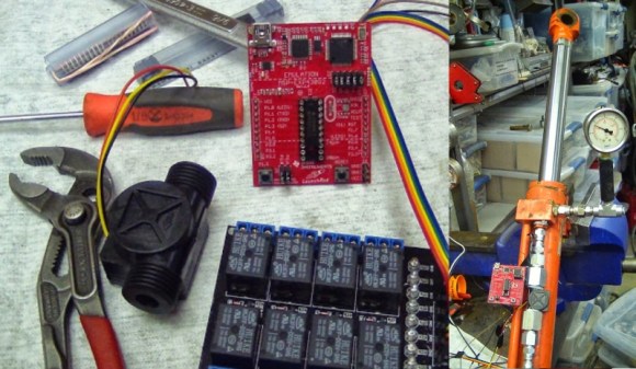
Anyway, he recently picked up old hydraulic cylinder for next to nothing, and decided to try messing around with it. He purged the oil out of it and is now using it as a pneumatic cylinder. He also picked up a cheap $10 plastic Adafruit flow meter, and decided to try to make a positional pneumatic cylinder. Using a Launchpad development board, he controls the solenoid valves using a Dangerous Prototypes ATX breakout board. Surprisingly the cheap Adafruit flow meter was sufficiently accurate enough to measure the amount of air in the cylinder, which, depending on the load, can be used to position the cylinder, somewhat accurately.
He ran a test of about 360 cycles before the flow meter broke, and was able to achieve an accuracy of about 5mm! Not bad at all. Stick around after the break to see it in action — and to hear his colorful commentary.
http://www.youtube.com/watch?v=Gmt7iVCwDKY
[via Dangerous Prototypes]


How do you hold it in position? Hydraulic pistons tend to be all or nothing.
Ahh, fixed volume of air = relatively repeatable positioning. Wonder how it would fare with a load and how much force 120 PSI can generate?
Poorly. Without load you’re close to atmospheric pressure inside the cylinder, so, putting even a load on the cylinder will compress it half way in.
One way of achieving positional and load accuracy with pneumatics is to pressurize both sides of the cylinder to some high pressure so that when both ends are closed the cylinder won’t move. The higher the pressure, the stiffer it becomes. One way of achieving that is to put a pressure regulator to your return line so that the outgoing air must be forced out.
The guy is kinda doing that by plugging the other end of the cylinder with the gauge and using the pressure inside as a return spring. That works, and you could also deliberately pump in pressure and add a piece of pipe to act as dead volume so the movement of the cylinder won’t change the backpressure so much.
He’s got about 100 kPa of pressure inside as the cylinder is extended, which is something in the neighborhood of 50 Newtons of force with that cylinder. It’s enough to hold up a jug of milk.
The real way of having a professional system is with a valve 5-3 to block the position you have to put the valve in intermediate position. The system that I usually install use a linear POT connect to a PLC with a PID. Some times I control speed and position by adding a proportional valve.
Air cylinders will not hold position accurately, nor for very long, because of the volume differential caused by the shaft. Nominally, the smaller the diameter of the cylinder, the more effect the shaft has on the volume (exclusions apply for very small shafts in small cylinders and very large shafts in large cylinders). Any of the texts on pneumatic cylinders and position holding talk about this.
i have been reading HaD and watching the videos for years, and YOU sir are the owner of the most entertaining video. at least the commentaries are craking me up…wait it might be the cabernet sauvignon.
Or the Carbernnabis Savuvigiggle.
That cracked me up great vid thx HaD.
It seems a little odd to expect a flow meter to handling positioning especially given air is compressible and with changing loads on the piston, the position wont hold.
I have been wanting to use pneumatics for a while on the steering on my robots but I have always been worried about overshoot like this. The designs I wanted to use mainly comprised of a PID motor controller with a potentiometer feedback to handle position measurement. Due to the complexity, I just went with a high speed linear actuator with feedback, but perhaps I need to experiment with air. The robots do have onboard air after all and the actuator overloads easily if I have too much weight on the front which can be a bit annoying.
Seems a backwards step to empty the oil out as hydro oil is incompressible and the power density is many times that of air. Many modern cars have 12v hydraulic pumps for their steering, or you could drive an old-fashioned belt type one with an electric motor. Then you have regulated pressure through a valve of known aperture, so movement of piston becomes pretty much proportional to the time the valve is open for.
A friend of mine used mini- and micro- pneumatic cylinders filled with hydro oil (or car brake fluid, which is thinner) as actuators to good effect.
“Shit the bit”…that’s a new one for me…
Pretty sure the phrase is “Shit the bed”
This is not new, and performance in proprely designed systems is extremely accurate and rigid.
http://en.wikipedia.org/wiki/Electrohydraulic_servo_valve
http://www.festo.com/cms/nl-be_be/9530.htm
I’ve seen a decades old machine tool that uses hydraulic cylinders for linear motion, and can move what appears to be several tonnes of metal with sub-thou accuracy.
That was before computers as well, so the whole feedback loop is mechanical. The valve is controlled by the distance between the machines true position and its desired position (which is moved via screw).
>sub thou
really?
use metric please.
Was he giving a specific number, or conveying an idea as to its accuracy? Did it do that effectively? Yes? Good, then shut it.
This isn’t hydraulic – it’s pneumatic. So not very precise at all
The second link is the one I think you are looking for.
but it’s not volumetric but based on sensing position
Back when I was in technical school, we had a pneumatic cnc plotter. It worked surprisingly well. I don’t remember very much, but I think it was factory-made. I’ve never seen anything like it before.
Oilfield hand by any chance? In Europe we prefer Private.
“That’s not really suppose to work!”
*supposed
This isn’t as precise as it seems – mind you that the air cylinder diameter is fairly large. I guesstimated that each 5mm of travel (that’s the precision he achieved) translates to about 15cubic cm of volume (or displacement to be more precise because if it is compressed air then at 10 bar we get ~ 150ccm). For an air cylinder that’s 15mm in diam 15ccm means roughly 10 cm of stroke lenght so not very precise at all. That’s the problem with volumetric systems. Not to mention that such a system should not be used with compressible fluids.
I am not trying to be negative. Personally I would use a hall effect sensor such as ss495b or similar. Obviously you’d need an air cylinder with an inbuilt magnet but these days most manufacturers have them.
It IS possible to get accurate positioning of a pneumatic actuator, even under changing loads. It’s done in industrial control valves all the time.
The trick is to use a positional feedback mechanism to compare the current position vs. the input signal. This creates an error signal which then constantly corrects the (usually) double-action cylinder. They are very reliable and repeatable.
Several controls companies (Fischer, for example) make controllers that are 100% pneumatic for unpowered applications (such as middle of nowhere gas pipelines).
http://www2.emersonprocess.com/en-US/brands/fisher/positioners/PneumaticPositioner/3710/Pages/Fisher3710.aspx
Lots of colorful commentary in the video but it could have been beeped out or redone/edited out…
Why would it need to be “beeped out or redone/edited out” are we all not adult enough here to hear such language?
Indeed. But without the colorful metaphors, I wouldn’t have understood anything else he was trying to convey. Substitution ‘family safe’ verbiage instead of bleeping out the metaphors would have made it so humorous, it wouldn’t seem like a serious endeavor he had been working on.
Basically, words are nothing more than elaborate sounds. If you find any particular word unpleasant or offensive, you should find them ALL offensive – and bleep the living fuck out of everything everyone says….
I was quite interested in the subject and enjoyed the ‘delivery’.
any idea about how to get a one way pneumatic electro valve to buy?