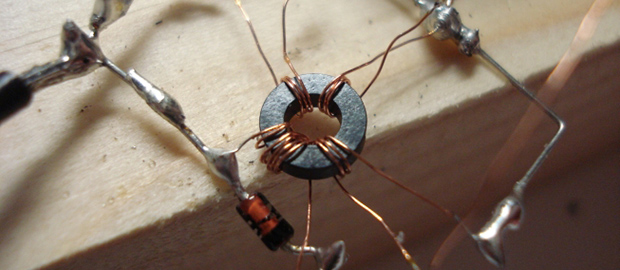
We’ve seen NAND and NOR logic gates – the building blocks of everything digital – made out of everything from marbles to Minecraft redstone. [kos] has outdone himself this time with a logic circuit we’ve never seen before. It’s based on magnets and induction, making a NOR gate out of nothing but a ferrite core, some wire, and a diode.
The theory of operations for this magnetic NOR gate goes as follows: If two of the input windings around the core have current passing in different directions, the fields cancel out. This could either be done by positive or negative voltages, or by simply changing the phase of the winding. To keep things simple, [kos] chose the latter. The truth table for a simple two-input, one-output gate gets pretty complicated (or exceedingly cool if you’d like to build a trinary computer), so to get absolute values of 1 and 0, a separate ‘clock’ winding was also added to the core.
One thing to note about [kos]’ gate is its innovation on techniques described in the relevant literature. Previously, these kinds of magnetic gates were built with square ferrites, while this version can work with any magnetic core.
While this isn’t a very practical approach towards building anything more complex than a memory cell, it is an exercise of what could have been in an alternate universe where tube technology and the transistor just didn’t happen.


Are you sure this is a NOR? Sounds more like an AND as far as I can tell from the description here.
No, it says there is a cancellation effect going on when both sides are active. That sounds more like XOR than NOR, but I could be misinterpreting also and be wrong.
Truth table for a 2 input – 1 output gate complicated? Its just 3 columns and 4 rows and for a NOR should be:
0 0 1
1 0 0
0 1 0
1 1 0
Ah, Kos’s page gives “1 1 -1” for the last line. There y’go! It’s not generally interchangable for a transistorised gate, and would need buffers if you were going to connect more than a couple together.
I wonder how much electromagnetic logic was ever made? Obviously not counting relays.
Can anyone think of an “inductive logic” joke that’s funny?
Yeah, I just read his page. Seems -1 is reverse current flow, diode then prevents this to effectively render -1, 0.
Look up “Setun” (http://en.wikipedia.org/wiki/Setun) it was built on similar logic.
Nice counting in binary there genius.
the hell is that meant to mean? I wasnt counting in binary, I was writing the truth table for a logical NOR.
I think he means that generally you count up in binary for truth tables e.g
A B f
0 0 1
0 1 0 * These two were the other way round in yours
1 0 0 *
1 1 0
No big deal as far as I’m concerned, there was no need for the sarcasm:)
and sometimes you’ll count 00 01 11 10 when you’re writing out tables of states.
(if you were making a karnaugh map)
Really depends what you’re doing, all he really did was swap MSB and LSB, I don’t see the problem.
I think you’re giving Mr Random more credit than he deserves. One of the most brainless of snarks, is one where you’ve no idea what he’s actually complaining about, and it doesn’t seem clear whether he knows the correct answer himself.
Perhaps seeing a list of short trinary numbers made him think Mr Six there was counting in binary, perhaps Random doesn’t know what a truth table is, or doesn’t pay a lot of attention when he’s reading? Perhaps he’s the world’s foremost expert on trinary mathematics, and that’s what happens to your brain when you do that for too long?
He got more understanding and patience in the replies than he showed himself, in his misunderstood criticism of something that was correct.
Sorry, segmentation fault. Only half of what I posted made the sense I imagined. How did trinary get in my head?
I’ve always been taught (and shown examples of) truth tables with the A input alternating repeating 0 and 1 as you go down the column, B input 0, 0, 1 ,1. C as 0, 0, 0, 0, 1, 1, 1, 1.
Only time I havent seen it that way was 1 lecturer at uni who essentially reverses my order.
The circuit used has 3 inputs(a,b and a clock) so if it is binary it has 8 combinations.
I think though that it is a trinary gate thus 3^3 = 27 which is some what complicated.
I like binary so i might have made an error on the trinary colculations.
They nice hack.
nope it’s still binary.
same as 3 and 4 input TTL gates are still binary, (not trinary or quadrinary).
Although llittle known today, Magnetic Logic is actually well over 50 years old… It was successfully employed in the CPU design of the British built Elliott 803 computer – see http://en.wikipedia.org/wiki/Magnetic_logic and http://en.wikipedia.org/wiki/Elliott_803 for further information. I remember seeing such logic elements myself in the 1970’s – my colleauges at that time included computer maintenance engineers who still worked on the 803, a working example of which is preserved at the Museum of Computing at Bletchley Park in the UK.
The roots of magnetic logic go back much further.than that. When I was exposed to the technology some 30 years ago, I was taught that magnetic amplifiers were developed to boost telegraph signals over long distances. The Google patent search turned up a publication on the method dating back to 1916! Granted, an amplifier is not quite the same as binary logic, but an amp driven into it’s non-linear response range makes a very handy switch, the basis for nearly all digital logic circuits used today.
Interesting. There is a connection, although magnetic gates and magnetic amplifiers are not quite the same thing. The logic gate designs took advantage of the hysteresis characteristic of the cores. For the AND function, the flux from two (or more) input windings would be needed to cause a change of magnetic state in the core. The switching “blip” would be picked up in the gate’s output winding. For the OR function, the input windings and drivers would be designed such that any input current could change the magnetic state and thereby give an output signal.
Sure, just like a transistor, a magnetic amplifier becomes a logic gate by driving it into the non-linear region, where it swiftly switches between two states. Of course, a binary gate and a transistor amplifier aren’t quite the same either, but you can build logic gates using transistor amplifiers, just as you can build magnetic logic using magnetic amplifiers. My memory is a little fuzzy on much of the details after so much time. I wonder, where did you pick up details of such an obscure technology?
The first company that I worked for (Systems Reliability Limited in the UK) held maintenance contracts for many computers from the 60s. I joined them mid-70’s and worked on a very wide range of gear from that period – processors, tape drives, punched card readers, etc. Some used standard logic families such as TTL, DTL and even ECL. Others used discrete diode and transtor logic, but among the many parts that came across the bench were some of those magnetic logic blocks as used in the Elliott 803. I also came into contact with magnetic core storage of course – a very specific application of the same technology.
That sounds like such a fascinating job! Was magnetic logic the most obscure technology you encountered, or where there even stranger things that lay beneath your oscilloscope probes?
Certainly it was among the more obscure. I remember seeing magneto-restricive delay lines as well (used as a serial form of storage in a few old machines) although I never worked on them. There would sometimes be a few valves in old high voltage power supplies. Most stuff I worked on at that time was actually designed in the 70’s, so standard logic was the order of the day. At least one got to find out how processors and things really worked.
I’ve read about delay line memory, it always sounded like you’d really have to code really close to the metal to get the timing work. Can’t imagine revising a memory intensive program without a lot of rewrites. Forget multitasking, even a real time operating system would probably be too much overhead. Sounds like fun!
Now someone needs to make a trinary inductor based computer. That would be awesome.
There were a few in the 50s and 60s. I’m thinking the most advanced one was made in Poland/Czech/Somewhere around there.
A quick google shows that there have a been a few trinary/ternary computers made, one was made in Moscow. Interesting.
And they were all horrible to work with, right? Or did everyone just use 2 gates to give octal and forget about using the “8”?
Can’t think why you’d want to, I’m sure it’d cost more transistors using modern methods on chips. Maybe it helped for whatever crazy stuff they made their computers out of.
The Amstrad CPC used trinary in it’s colour look-up table, giving x out of 27 colours. But that’s not really important. Only perhaps saved a couple of wires somewhere in the ULA. You still programmed the colour registers in binary.
“I’m sure it’d cost more transistors using modern methods on chips.”
Where do you get that from? The Wiki about SETUN shows that an equal binary system cost 2.5 times.
“And they were all horrible to work with, right?”
It’s programmed in something like FORTRAN, so no different to ‘normal’ systems.
But it is different to anything you are used to, so it’s bad.
Haters gonna hate….
@NotMe
It was something like Forth (FORTH). Very different from Fortran.
The hysteresis loop in magnetic logic only has a high/low bistable state, it would take a fair bit of external circuitry to program a tri-logic state, or some creative use of the “dead band” between high-low states.
Jeri Ellsworth made a very informative video about magnetic logic a while ago:
http://www.youtube.com/watch?v=p7SkE5pERtA
I was thinking I remembered the same thing.
Fantastic video explaining the principles of magnetic logic. Thanks for sharing.
I think this is relevant to the ferrite cores used in space computers. They’re some kinda special to keep 1’s from becoming 0’s with just a stray high energy particle burst
About halfway down the page, there’s a figure for what the author describes as a “reverse sawtooth generator”. Can anyone explain this arrangement? It looks to me like the PNP transistor is part of an emitter follower, with the NPN establishing some sort of bias, but the NPN has current flowing from emitter-to-collector? And base-to-collector?
I think this is the technology that powered apollo guidance computers in moon landing hah …
Somewhat similar, but not the same. Core memory was used for working memory, with 2D arrays of cores being magnetized in one direction or the other to store data…no computation was done magnetically.
Core rope memory was a completely different approach that literally hard wired data in the form of wires going through or around cores in a long rope. The read mechanism was transformer action, the cores weren’t magnetized. The word select lines operated by forcing sets of cores into saturation, leaving one un-saturated core to act as a transformer…thus each core stored a full word and doubled as word selection logic. Much more compact than standard core memory, but read-only.
Discovery Channel’s “Moon Machines” has a good bit on the “rope memory” technology, including footage of the ladies threading magnetic memory.
Somewhere aroung here I have a 50-year (or more) old IBM book devoted to magentic logic circuits and magnetic amplifiers. A DC current in one coil can partially saturate the core, modulating pulses or AC waveforms coupled through other coils. Some switching circuits relied on full core saturation. A lot of really cool stuff there, without any exotic semiconductors needed at all…
The downside is power requirements and component size. It would be an interesting thought experiment to apply modern fabrication techniques to the 100 year old technology. Surely there must be a way to automate the hand threaded magnetic cores of old by now. Would be interesting to etch and deposit cores and windings directly using photolithography/deposition techniques. My gut feeling is they would still have higher current requirements and larger feature size compared to even early CMOS.
Looks like I spoke too soon: New milestone could help magnets end era of computer transistors. Seems magnetic logic is now being toutes as the newest savior of Moore’s Law!
Sounds a bit like Bubble Memory – anyone here ever played with that? I looked at datasheets (late 80’s I think) but never took it any further.
Bubble memory has its origins in magnetic core memory, yes. There was a lot of development between the two technologies, though.
Hi guys,
Thanks for all your comments. I was not aware of the Balanced ternary, this is new to me so I will definitely have a closer look at it, thank you.
Now do not get confused, the approach I have followed for this gate is not based on square loop ferrites. It does not need such special ferrites and it does not depend on any current to drive them into saturation and out of it, effectively using the core as a bistable device. That is the difference.
It was inspired from the coincident current magnetic core memory, but there the coincident currents use the switching properties of the core again, whereas in my approach they don’t.
The gate uses normal transformer action with coincident currents setting accordingly the output at the time the pulses occur, but not “storing” any state in the core. Read the page carefully. The “magic” here is that you can use any transformer at any size, there is no limitation. Theoretically you could even use a KW mains power transformer to do the same thing, as long as you could have strong enough input pulses.
And Yes it is still binary logic(because of the diode used), the clock is used to satisfy logic conditions and to perform a “read now” function. Whenever the clock pulse goes into the gate, only then the output should be read by the next circuits/stages. I have not found a reliable way to do it without a clock.
The purpose of the reverse sawtooth was to minimize unwanted opposite polarity pulses into the gate.
Another advantage is that “logic levels” can be anything (depending on the transformer insulation, from mV to KV as long as they kept consistent throughout a system. In contrast, logic levels in square loop ferrites were strongly depended on the ferrite properties used.
Oh, btw I do not think space radiation would be a problem in my approach (well it will be for the diode)
It would be interesting to see how many levels this approach could achieve without using amplifiers.
Linked page is gone.
But for what appears to be the source material see:
Logic Circuits Using Square-Loop Magnetic Devices: A Survey
http://ieeexplore.ieee.org/xpl/articleDetails.jsp?arnumber=5219189
Perhaps also the other references listed in the “Unusual computer components” section of:
Design of Digital Computers: An Introduction, by Hans W. Gschwind
https://books.google.com.au/books?id=4vXxCAAAQBAJ
This technology is still used and very common in high integrity safety systems because of it’s inherent fail safe behaviour. “Solid state logic solvers”