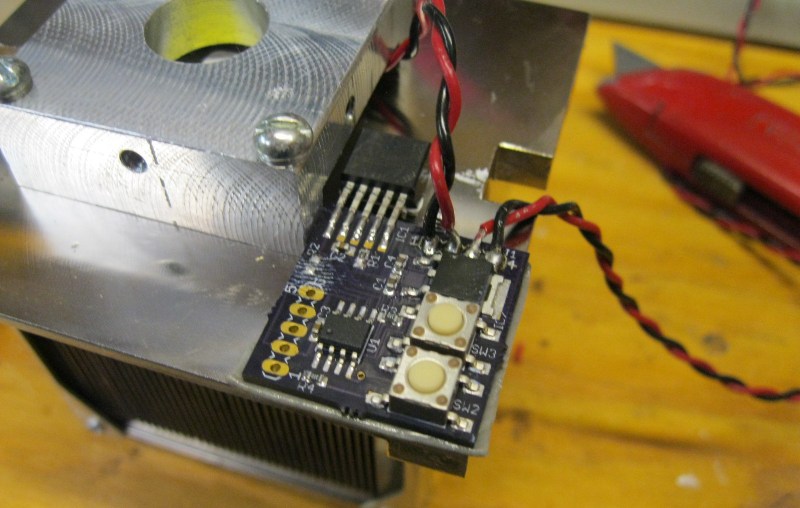
[Peter] needed to drive a high power LED for his microscope. Rather than pick up a commercial LED driver, he built a simple constant current LED driver and fan control. We’ve featured [Peter’s] pumpkin candle LED work here on Hackaday in the past. Today he’s moving on to higher power LEDs. A 10 watt LED would be a good replacement light source for an old halogen/fiber optic ring light setup. [Peter] started with his old standby – an 8 pin Microchip PIC. In this case, a PIC12F1501. A PIC alone won’t handle a 10 watt LED, so he utilized a CAT4101 constant current LED driver from ON Semi. The PIC performs three tasks in this circuit. It handles user input from two buttons, generates a PWM signal to the LED driver, and generates a PWM signal for a cooling fan.
Control is simple: Press both buttons and the LED comes on full bright. Press the “up” button, and the LED can be stepped up from 10% to 100% in 10 steps. The “down” button drops the LED power back down. [Peter] even had a spare pin. He’s currently using it as an LED on/off confirmation, though we’d probably use it with a 1wire temperature sensor as a backup to thermal protection built into the CAT4101. It may be overkill, but we’d also move the buttons away from that 7805 linear regulator. Being that this circuit will be used with a microscope, it may eventually be operated by touch alone. It would be a bit surprising to try to press a button and end up with a burnt fingertip!


Why not use a switched mode current regulator? Now he’s emitting 6W of power in heat. With a switched mode power supply, the fan may even not be needed anymore.
I’m no electronics genious, but having that much heat means a lot of wasted energy, I can’t imagine there being more efficient ways …
Using a switching constant current source instead of a linear constant current source would be my first try..
You would need external inductors to make it work, and adjusting the current would be more difficult than a simple current mirror.
There are lots of switch mode chips to choose, LM3405A is a nice one, just set the current with one resistor, one tiny inductor, and off you go.
@Dax there are plenty of cheap chips that with a couple of extra components can include current limiting. When you hit the limit you effectively turn it into a constant current supply. It’s the foundation of the cheap switching voltage regulators come battery chargers come LED drivers available on the internet.
it is well known that linear regulators are far more inefficient than switchmode regulators.
Not necessarily, if your input voltage is close to the forward voltage drop of the LEDs.
For example, imagine that you have a 120 volt supply and you connect 115 volts worth of diodes to it. The leftover 5 volts at say 300 mA is 1.5 Watts whereas the string of diodes is 34.5 Watts, so that’s 95.8% efficiency even with a linear regulator.
So clearly replacing the linear regulator with a more expensive switching regulator gives you no real advantage, and it’s actually a worse choice because then you have to deal with EMI noise from the switching.
what you said was technically correct, for DC, like in this project,
but you mentioned 120v without mentioning AC or DC? sinewave? squarewave? ect?
switchers (SMPS) can, and often do, have efficencies between ~75% and ~99%.
how much heat does your desktop computer put out from powersupply-fan?
if its 250w nominal at less then 20w heat output (heatsinks after electrical isolation do NOT cause burns, means it must be WAY less then 25w!) converts to a 90% or more efficency
120v AC can NOT be calculated that way, unless you want a low-power,
low service-life light that will have HUGELY bad power-factor and be very flickerey.
oh, did i mention VERY dim-looking, even at the LEDs max current???
read on to see how i calculate a 16% brightness when “run at” the max current compared to a LED running on linear DC at it’s same max current
in LEDs run direct from 120vAC, you have to use a large voltage drop on the resistor, otherwise the LEDs would only be able to be switched on when the AC is greater then the V-LED, remember the AC pulses up and down smoothly and is only at the top part for a small percentage of the time!
peak voltage is 120v * 1.414 = ~170v
so assuming a triangle wave,
your 115v diodes would only be on for;
(170 – 115) / 170 = 32% of the time
but its AC not DC so its HALF that time because the diode is only one direction
so we get 32% / 2 = 16%
kinda crappy considering a PWM controller might be able to operate the LED independant of the instantaneous voltage or polarity of the AC
in other words, theres no such thing as an LED christmas-light-set with the advertised 98% efficency!!!!!!!!!! GOVERMENT APPROUVED LIES!!!!!!!!!!!
it is only when you add on complex circuitry that you can achieve anywhere near 95%
it is the LEDs themselves that are 95-99% efficient
If the fins of the heatsink were facing up (instead of down), it should be able to stay reasonably cool even with passive convection, linear or switchmode regulation ;-)
For a microscope, light must go up…. Dificult to put the heatsink over the light source.
For a buck at the dollar store you can have enough mirror for 10 microscopes.
The direction of the light also depends on the style of microscope ie; transmitted vs reflected light.
he he , Dollar Store is my source for lots of basic parts at near wholesale price. Ebay provides P W Modulation LED controllers at such low cost today i can’t begin to waste my own time building my own. As an older EE and logic/software designer, i love reading how new hackers ‘rediscover’ what i’ve been doing for the last 20 years! but throw in some Ardunio parts and kazamm, a whole new set of possibilities emerges! ;-)) light up the planet!
After looking over the schematic, it would seem the vreg is only providing regulation for logic level. It isn’t doing anything to regulate voltage for the LED itself. That said, I doubt the constant current driver and the PIC are pulling all that much current on their own; the PIC datasheet mentions 150mA MAX and the LED driver doesn’t seem to say how much current it requires. I doubt the “burnt fingertip” would be much of a concern either.
My back of napkin calculations indicate about 3W on the higher side of things. He is feeding his vreg w/ 16V as per the instructables link.
I could be speaking out of my butt. I am sure a smart person will correct me if I am completely wrong.
The final mounting is horizontal to mate up to the fiber optic whip from my scope. The need for the fan was marginal even with the heat sink as shown. After about a half hour the heat sink was very warm to the touch but not so hot it would hurt anything. Just went with the fan for maximum LED life (HS stays cold even at 25% fan speed).
On the topic of regulators:
5V reg only supplies ~10-20mA to the card. Basically it just runs the micro and the control logic in the CAT4101. Never gets above room temp even after hours of running.
The CAT4101 is linear but if you pick your power supply within reason it is a good choice. The LED I am driving is a 12 – 14V unit off a 16V power supply. So about 4W worst case but more likely around 1 or 2W. Mostly decided to go with it to keep complexity down as it only requires 1 critical external part (set resistor). Some point in the future will tackle a switch mode boost to drive some 30V leds off 12V.
Hmm, those were some crazy camera artifacts when the LED was exposed and being driven with PWM. I wonder if [Peter] will be using a digital camera with his microscope, and if it will have any similar issues?
Wow, that thing is incredibly over-engineered. For the same effect (he’s using a regulated switching PSU, after all) he could just as well have used a resistor for current limiting with a transistor hooked up to the PIC for PWM.
Now, i’d like to mention that one can buy a ready-made adjustable CC/CV (2A) buck converter for about 3$ on ebay. Add a simple pot to the right spot and it’s even dimmable, all probably for less than just the PCBs of his project cost. As a bonus, you’d even get flicker-free light with that.
That depends on what sort of power supply he has. With some random “16 Volt” transformer, the current will fluctuate a lot and risk damage to the diodes because it depends on the load and the line voltage.
A quick google run turned out that 16V/4.5A typically is an IBM ThinkPad PSU, of which i’d expect pretty good regulation.
Of course, a simple resistor would be a bad idea if you’re using a PSU that does not provide a stable voltage, but for this case it would be totally fine.
Your dead on that is where the brick came from (T40 to be exact I think). Mostly went with the CC driver for the ease of PWM input and the fact I would not have to calibrate the current limit resistor to every LED I would buy (The LED is actually a string of 9 dies and the exact forward voltage per current can vary greatly from batch to batch.
The eye light sensitivity is not linear but sort of logarymic (http://en.wikipedia.org/wiki/Weber%E2%80%93Fechner_law).
No one should use a linear law for a dimmer.
But everybody do that :(
more on this:
http://www.j-robotics.com/how-to-dim-a-led-properly-for-the-human-eye/
Will have to give that a try sometime. Easy enough to update the step levels in firmware.