It’s pretty well known by now that the LED pixel hardware which is starting to be commonplace, both WS2811 and WS2812, needs pretty strict timing in order to address them. There are libraries out there which mean almost no work on your part, but that’s no fun. [Elia] started looking into what it takes to drive the hardware, trying out a few 8-bit micros before moving to 32-bit with the help of an STM32VL Discovery Board. The move to a beefier processor brings a lot of speed, but why bit bang everything? He came up with a way to use the PWM and DMA features of the chip to drive the LEDs.
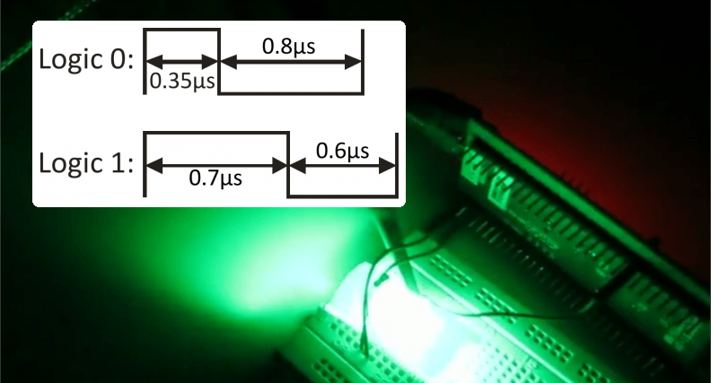
DMA is the Direct Memory Access unit that allows you to change the values being sent to the pixel without interrupting the processor. This is done by pre-loading the data at a memory location. This buffer is automatically read by the DMA unit — its values are used to set the PWM timer compare trigger in order to send out logic values show in the diagram above.
If you do want to delve further into this topic here’s a collection of techniques for driving the WS2811.


Hmmm… no mention of my OctoWS2811 library, which has been doing this DMA-based approach for quite some time. In fact, most of the large-scale LED projects that have appeared here on Hack-A-Day over the last several months all used OctoWS2811.
” both WS2811 and WS281″ ???
WS2811 is the Controller IC, whereas WS2812 and WS2812B are the LEDs with Controllers built in …
Sorry Paul. didn’t mean to reply but rather post normally :)
Reading through the article and code, this DMA approach is indeed different than what I did.
Elia’s approach uses DMA to rewrite the timer’s compare register. Each cycle of PWM gets its duty cycle adjusted by writes from the DMA controller. The output signal is a PWM waveform from the timer. In Arduino terminology, this is like using analogWrite(), where the DMA engine is setting a new PWM duty cycle each waveform period.
In OctoWS2811, I created two fixed duty cycle PWM waveforms. The waveform edges trigger DMA transfers to the port output register. The output signals are ordinary digital outputs that are being rapidly rewritten by the DMA controller. In Arduino terminology, this is like using digitalWrite(), where the DMA engine is driving the pins high and low.
Maybe right about now you’ve realised you aren’t the only one using these things or has a library for them? Maybe your hat size will come down a notch or two.
I’m using the OctoWS2811 library to drive some WS2812B strips. I was also surprised that there wasn’t a mention. I’m glad Paul mentioned his library. (props to both approaches!)
Actually, both approaches have their advantages and disadvantages.
Paul’s library looks excellent (and the idea is very clever), but is really designed for driving eight strips at a time, using pre-processed data. If you only want to drive *one* strip, the approach doesn’t really fit. I plan on doing something similar, but for driving just a single strip.
The approach described in the article above is very heavy-handed. You need a buffer with 24 *bytes* of RAM for a single LED. I considered this approach in my work and rejected it — it simply doesn’t scale and won’t work at all on smaller devices.
One problem with this approach is that it requires offline proprocessing with a huge memory footprint. If I understand correctly, then every 24bit=3byte RGB value is blown up to 48 bytes of intermediate data.
Fortunately one can use the double-buffered DMA configuration. The preprocessing can be done in an interrupt a block at a time, so that not as much RAM is required.
Someone needs to figure out how to make little PicAxe devices talk to these. you really need some processor speed to talk to them. or someone design a WS2813 that doesnt require such strict timing.
someone did, the WS2801 predates the 2811/12 and as long as you keep the delay between bits below 500uS you are ok, downside is it needs both 2 pins to drive (clock & data) and they don’t make a integrated LED version.
SW: +1
HW: -1
I drive these with almost no load using the PRUs on a beagle bone black and some interrupts to sync the transfer between the code running on Linux and the PRUs. The timing isn’t actually that strict .. My divider settings for the clock that shifts out the bits is pretty far out and it works just fine.
I’m also using the BeagleBone Black PRU to drive up to 48 of the strips in parallel, also with near zero CPU load on the ARM. It’s very convenient to have a programmable realtime system grafted onto the very flexible Linux system. I just recently added OPC receiver support to make it easy to draw to the strips from Processing or other tools. https://github.com/osresearch/LEDscape
Hmm I was planning on doing this with a chipkit and some led panels I have laying around.
Note that the timing on the WS2812/WS2812B LEDs has changed as of batches from WorldSemi manufactured since October 2013, and timing tolerance for approx 10-30% of parts is very small.
Recommendation from WorldSemi is now: 0 = 400ns high/850ns low, and 1 = 850ns high, 400ns low.
I have a plan for a library that will drive 8 strips ( http://www.ledlightinghut.com/144-led-m-ws2812-digital-intelligent-rgb-led-strip-light.html ) simultaneously, using DMA so the CPU isn’t tied up bit-bashing the waveform. That will allow it to generate animations or communicate by USB or serial while also updating the LEDs. The idea is to support up to 2000 LEDs with double buffering or 4000 LEDs with single buffering, at 60 Hz update rate.
At this point, it’s in the planning phase……
Thanks for your post!!
https://www.instagram.com/p/BaLvD8KBIP9/