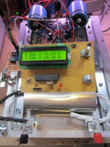
[Kerry] set out to build a digitally controlled dual supply for his bench. He’s already built a supply based on the LM338 linear regulator, but the goal this time was to build it without a linear regulator IC, and add digital control over both the current and voltage.
In part one of the build, [Kerry] explains the analog design of the device. He had an extra heatsink kicking around, which can dissipate enough heat from this linear supply to let it run at 10 A. A NE5532 opamp is used to track a reference voltage, which can be provided by a DAC. The current is measured by a LT6105 shunt sense amplifier, then compared to a reference provided by another DAC.
Part two focuses on the digital components. To interface with the analog circuitry, two MCP4821 DACs are used. These are controlled over SPI by an ATmega328P.
Fortunately, [Kerry] also has his own DC load project to test the supply with.


You can still use a linear regulator with all its built-in goodness by
apply a DC offset to its feedback loop. They have good respond time,
good PSRR, built-in short circuit and thermal protection.
Thermal protection is important in a linear bench supply.
I have been looking at this on eBay, not sure if it works but at least seems promising and cheap:
http://www.ebay.com/itm/DC-DC-300W-13-62V-zu-0-60V-Digital-controlled-Programmable-Power-Supply-Module-/181058741306?pt=Bauteile&hash=item2a27f1243a
So the max input current is 5A, with a voltage range of 13-62V. Assuming you were to power it at 13V that would mean it has a maximum input draw of 65W. How the hell is it going to put out 300W? And if you want all 300W, who has a 62V DC power supply just sitting around? Also those heat sinks seem awfully small, I have a cheap Chinese dual (i think) 0-30V 2.5A power supply and the heat sinks on it are much larger than this.
I have a couple of Xantrex HPD60-5 (60V/5A)bench supplies that I fixed
up. Very useful for testing things. :)
I would guess the larger heatsink with probably a MOSFET mounted is good
for 5W or so. The smaller one is for schottky. You could lower the diode
drop if you run the diode hot.
Given they don’t use a sync MOSFET, the 95% efficiency figure is more
likely to be a peak near 1/2 load.
The sad part is that their board layout isn’t ideal. They mounted the
heatsinks backward, so the fins are facing the tall caps instead of the
edge of the board where they could get a bit better convection. The
middle cap is sandwiched between the inductor and a power resistor for
slow roasting. :P
I’m just playing with building a bench supply designed around some of http://www.ebay.ca/itm/350869951366 not sure if I can use digital pots to control them.
Unlikely. They would have the trimpot on the high side of a voltage
divider with on terminal going to the output. That would likely go above
the maximum allowed voltage of a digital pot if you want more than a few
volts.