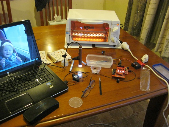
For Christmas, [Hamster]’s wife gave him a mini-oven. Later that day, he tore it apart and built this FPGA controlled reflow oven.
We’ve seen plenty of reflow oven builds in the past. Most of those projects use a microcontroller to do closed loop control, sensing the temperature and toggling the heating element to hit a set point. This build uses the Papilo One FPGA development board as a controller. It implements a state machine that meets the reflow profile of the solder paste, ensuring SMD components are soldered properly.
The oven uses a MAX31855 to read temperature from a thermocouple. This device provides amplification, cold junction compensation, and analog to digital conversion which spits out the temperature over SPI. To control the heater, a 40A solid state relay is used.
The VHDL code that drives this oven is linked in the writeup, and has some interesting bits for those looking to experiment with FPGAs. It includes an SPI interface, display driver, and the temperature state machine logic.


Wow, this is not an application where I would have expected a FPGA.
interesting how much more successful it would be if you used lets say dedicated pc with intel i7 cpu to control reflow oven?:)
Where would you attach the SSR trigger and the thermocouple ?
thermocouple ?:) hey there are at least 3 of them… one under cpu socket, one somewhere on mother board, one on gpu :) just desolder one, and solder one with longer wire :) for relay control i would use lcd 3d glass IR emiter led! easy just monitor notebook main boar temperature and switch on/off lcd 3d function :D i am joking… fpga is definitely on the best solution for such simple application…
I think this project didn’t start with “I have an oven, what’s the best way to control it?”, but rather “I have an FPGA board, and I want to learn more about it, so what’s a project that I can put it in ?”.
PC do not use Thermal Couple to measure chips temperature. They use diode junctions and that has an upper practical limit around 150C when the diode leakage is too high. FYI: Reflow peak is 240C Pb / 260C RoHS.
My soldering iron uses Thermal Couple and one I got from junk box uses RTD.
I was toying with the idea of using my Raspberry Pi so I could put a monitor on it – not as silly as it sounds as a Model A costs about the same as a Arduino Uno. However I like playing with FPGAs as a hobby and feel I get a deeper understanding of what is going on, I also have no shortage of dev boards sitting on the shelf, so the cost difference is zero.
I would like to think it annoys software hackers to have zero software in the loop, but am pretty sure they just roll their eyes, shrug their shoulders and say “I can do that it ten lines of [Perl | Python | C | Bash | Java | Whatever]”, or perhaps even worse “There is a PID library you can use for that at xyz.com”.
However true hardware hackers would most probably do the same thing with a couple of Op-Amps and 555 and a ripple counter…
Hey if it works it works. I would have gone with the Pi myself because I am a software guy and the price is actually really low. The other option would be a tablet and a small Bluetooth based controller. Of course do you really need more than a button and an LED as the interface for the reflow oven? Remember I am a software guy so that is really a question since I have never done a reflow oven.
You don’t *really* need anything more than an oven, a stopwatch, a multimeter with a long heat resistant thermocouple, You also need some way to control the power – a solid State Relay is really good, but you could also go lo-tech with a servo to flick a switch.
I doubt this will see that much use – I have 20 boards to make up at the moment, and then have to think of something new to make. Maybe once every other month I’ll use it, so when not in use I’ll just juse the dev board for something else.
But such a simple project did have its interesting bits – like how to convert the binary temperature into BCD for the seven segment display and RS232 interface. In hardware you can do it without using any division and convert an n-bit binary number in n cycles.
The other thing I find quite interesting is why other people use PID controllers – definitely overkill on the problem. …
The PID might help with 256 BGA devices. If you got a 3rd party to make 4-6 layer prototype PCB(s) for you. But if it is a simple single sided PCB, then yea you are probably right.
Title should be “An FPGA Controlled Reflow Oven”.
Thank me later.
I don’t get it?
F starts with a vowel, so you need ‘An’.
No. FPGA is an acronym and you put an before all acronyms.
http://www.drgrammar.org/frequently-asked-questions#36
Um….no. If you bothered to actually read the article you posted you’d see this:
“Before a letter or an acronym or before numerals, choose a or an according to the way the letter or numeral is pronounced”
As I scrolled down to get the reply button I noticed Will Lyon quoted the portion of the evidence you pointed us to as I was going to quote. I suppose there may be those who say I’m going to search the web to see how much an FPGA costs, but my guess there isn’t many who do so. Then again you wouldn’t be the first to use the wrong evidence to bust someone’s ball over something so trivial.
It’s also not an acronym, acronyms have to be pronouncable. Unless you’re all calling them “fpoogers” and nobody told me. It’s like “an LED”, like Will says, you pronounce it according to the first letter. Eg “A BBC production” vs “An NBC production”.
HaD editors fail English?
Unpossible!
Oh, and PIDs are <$15 off eBay.
You don’t learn as much when you buy a PID controller off eBay.
Sure, learning something is always fine, and controlling an oven is pretty simple project in the scheme of things.
That said I’d never build a temperature controller, even thought I know how PID works, I can program a uC etc.
My oven is a $15 PID plus a $15 timer. PID triggers an alarm at a set point, that trips the timer. Timer shuts off PID after x minutes. Yeah, it doesn’t get the profile right but that’s rarely critical in the DIY realm (and getting the profile right is a bit more complicated than just changing the temperature).
Look at the $15 eBay PID as a pile of parts. You get a case, power supply, probe (usually), ADC, uC, displays, relays and other assorted parts.
DIY will cost you hours of work and at least $50. After a while many decisions come down to “buy vs build”, and temperature controllers fell into the “buy” category years ago.
Same for building power supplies, Tx/Rx stuff etc.
Reminds me of the various lathe & mill groups where they spend all their time modding their machines – not actually doing anything useful.
Your time is limited.
Decide what’s useful. Copying this project isn’t (doing your own may be from a learning point of view).
Does ebay PID controller have timer for multiple stages of heating for doing proper reflow? i.e. preheat, soaking, reflow and cooling
Yeah, they do. Granted, those ones are a bit more than $15 though.
I really don’t understand why VHDL is more popular than Verilog. For some reason most courses focus on VHDL.
Because despite being wordier, it is more deliberate. There are fewer chances of making error due to the way it is structured. Notably, VHDL was standardised at the outset with a specific spec, Verilog had lots of different competing implementations that varied slightly.
For me, the selling point is the “2-process design methodology” (see http://www.gaisler.com/doc/structdes.pdf or http://www.gaisler.com/doc/vhdl2proc.pdf for more details).
This is not something I’ve managed to translate very well to standard verilog, hence traditional verilog designs tend to be much more verbose and ultimately ‘ad-hoc’. At least for me. Many more modules, many, many parallel always@ blocks, and the lack of decent ‘structs’ makes for 1000’s of signals/’wires’ all over.
An argument could rather be made for SystemVerilog; it seems to have most if not all properties needed for successful adaptation of “2-process” design. And additionally UVM etc for testbenches, as a bonus. I’ve yet to try synth’able SV for a full, non-trivial design though.
As someone pointed out: http://stackoverflow.com/questions/7285493/vhdl-vs-verilog
Europe: VHDL, America:Verilog
FPGA: VHDL, ASIC:Verilog
It is pretty easy to pick up the other language if you know one already.
Hardware people are too busy to getting work done than wasting their time like software types on making new languages/frameworks or fighting over them.
Later that day Hamster’s wife threw him out on the street. So tune in next week for how to make LED throwies in shopping carts!
Imagine the opposite – he buys her a drilling machine for christmas (obviously for his own needs), and she hacks it into a cooking mixer.
Nah. it was more like…
Later that day Hamster’s wife smiled about how her husband had such simple needs. Give him a $29 mini-oven,and it keeps him busy for hours. Who knew peace and quiet was so inexpensive?
Is there a good place online to learn about state machines?
I’m a mech. e., but I don’t know much about what they are or how to design using them.
While Hamster doesn’t say in his writeup why he chose to use a FPGA, but the thought that entered my mind was; that is this as good as project as any experiment with that technology. AFAIK Hamster is an old hand with using FPGAs and choose to use one here because he likes to use them. In any event I’m not sure why anyone would care. Hopefully we aren’t see the seeds of FPGA hate whenever the Hackaday writers post a project that uses FPGAs
“In any event I’m not sure why anyone would care. ”
No arduino to bash? :P
One of the issues with reflow ovens is the “Chicken & Egg” – building it usually involves soldering something. Using pre-built parts, like the Papilio, helps avoid that problem.