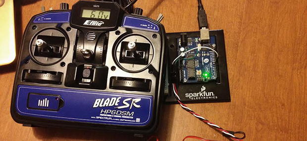
[SF Tester] (his real name, honestly, with a brother who does QA for Blizzard) recently picked up a Blade SR remote control helicopter. Compared to the cheap coaxial helicopters you can pick up from eBay or Amazon for $30, this heli is a huge step up, but it does have one weakness – it comes with its own transmitter, and binding it to [Tester]’s shiny new DX9 transmitter is a pain.
The initial attempt at getting the proper values from the stock transmitter into his big-boy transmitter originally consisted of taking the stock transmitter, some servos, attaching them to homebrew protractors, and reading out the values of each axis manually. That’s a brute-force method of improving his new toy, so [Tester] sought out a better method.
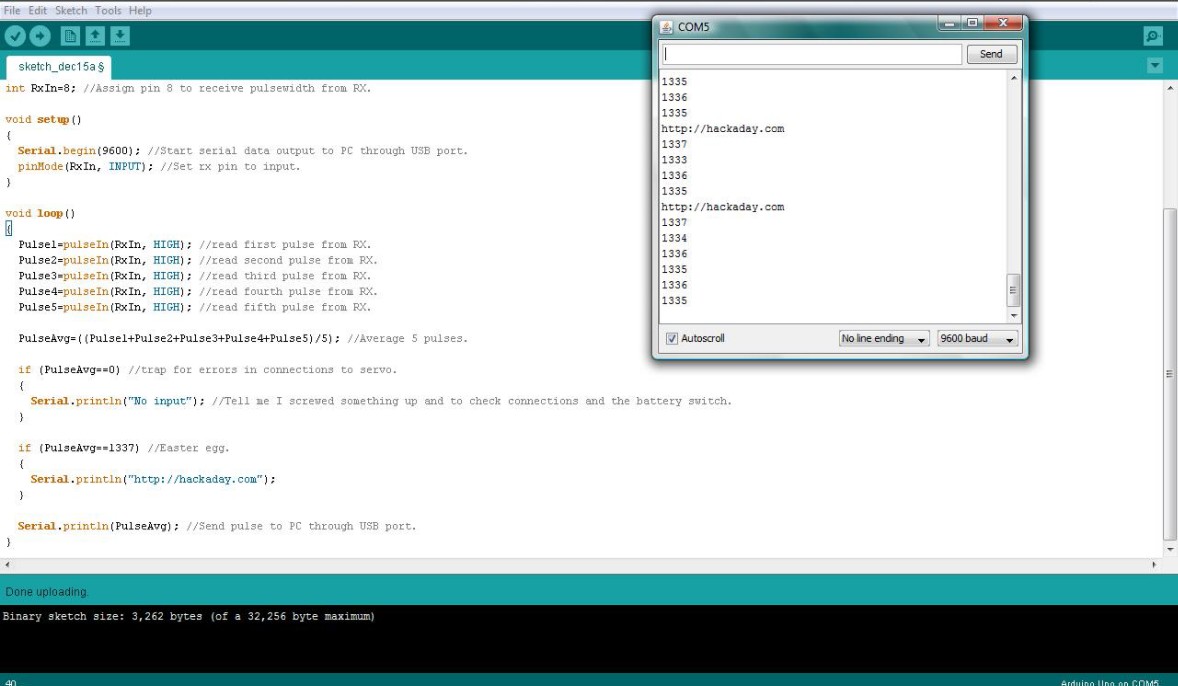
The solution came via Arduino’s pulseIn() command. By connecting the stock receiver to an Arduino, [Tester] was able to precisely read the values coming from the stock transmitter and import them into his very fancy Spektrum DX9 transmitter.
Every Fubarino contest entry needs an easter egg, so when the value of the pulses coming from the stock transmitter is exactly 1337 microseconds, the Arduino spits out Hackaday’s URL to the serial console. Cleverly hidden, and a great way to improve an awesome heli. We can’t ask much more than that.
There’s no direct link for this, but you can literally see the code in the image after the break.
This is an entry in the Fubarino Contest for a chance at one of the 20 Fubarino SD boards which Microchip has put up as prizes!


Not entirely sure from this write up what he has achieved here? So he can’t bind with the DX9, but instead is reading the PPM pulses from the stock TX to… read the values? And do what with them? Work out the channel order to bind with the DX9?
If binding is the only issue, then dismantling the stock TX, removing the module near the top of the box, and connecting the PPM, GND, VCC, BINDBTN – to the DX9 trainer port and now you have a ‘module’ that can control the heli (once you know the channel order as it looks like he’s already done)
His intent was to set servo end-points, neutral points and directions to be the same as in RTF transmitter. Both transmitters are Spektrum compatible, so channel order is the same, and well known: Throttle, Aileron, Elevator, Rudder, Gear, Aux 1,2,3.
Another issue is binding the heli in computer mode, selected by moving rudder stick after binding – to allow some more sophisticated configuration with computer radio such as the DX9.
Makes sense, he totally needs it all up on a blog page or something! :D
OK, the funny part there is that I actually do have a blog on RC Groups, but didn’t even think of putting it there.
Everything in the radio except the throttle curves was easily measured with a pitch gauge and going through each flight mode to check blade pitch, but there was no way to check the throttle. I’m used to using throttle governors, which mean there is no throttle curve, just a flat line that correlates to the requested RPM, and this speed control doesn’t do that, so i cheated.
The thing wound up being much more useful than I had expected, so I’m trying to convince an HD44780 LCD to work, then I can put the code on an ATTiny and stuff it all in an enclosure.
What? They are all basically made by the same company. How was he having so many problems? I don’t have a blade SR, but I have a DX9, a blade 120sr, and a Trex 450. I have had my DX9 bound to countless other RCs…and never even thought of needing something to read the pulses…
Isn’t that pulsein() command on an arduino servo tutorial?
I didn’t say I was having problems, this was just the fastest way to do it. Since the transmitter that comes with the SR doesn’t have any way to set endpoints, you can’t just dial up that screen and transfer those settings to a new radio like I did when I moved my Raptor E620, Mini Titan E360, or Blade 500 to the DX9. All of those have governors, so the throttle curves are a straight line. The SR doesn’t have a governor, so I could either spent quite a while figuring out what it wants, or just pull the info out of the old transmitter. The fastest way to do that was to see what the old transmitter was sending on channel 1 and duplicate it in the DX9. So a couple of hours in the air or 20 minutes on the ground.
And, no, that code isn’t from a tutorial. Yes, I used the pulsein function, but that’s just how it’s done unless you want to needlessly complicate the issues by writing the code by hand. Pulsein does the job with a single line of code, so why use anything else?
I’ve thought of doing a project something like this in the past. Buddy boxing two radios for helicopters is not a simple task if you can’t use the special JR or Spectrum buddy box modes. For example, I’ve seen a JR x9303 plane radio unable to use the special buddy box mode to a JR x9303 heli radio (both DSM2 radios without plug in RF module) because one of the channels (ail I believe) was reversed. So I’ve been forced to use the manual method of buddy boxing and you need to program in matching throttle and pitch curves, endpoints etc. Using a man in the middle box could allow you to automatically add required offsets etc.
Another problem I’ve seen is a DX5 buddy boxed with a X9303. The DX5 had so much offset on ail that the student always had to add roll input to keep a plane level. The DX5 trim adjust couldn’t zero out the roll.
sft2: If you have problems getting a HD44780 LCD to work, let me know. I’ve worked with these things back in the 80s when I created my first computer controlled radio. They are pretty straight forward and allow you to create special characters which I used for mixing arrows.
I finally gave up on that old LCD and bought an Osepp LCD shield. Got it all working last night and, other than being tethered to the laptop for power, it worked perfectly. The extracted throttle curves are transferred to the new radio and all is well. I even left the Easter egg intact.
Next step is to add a 2nd input so I can connect the source and target radios at the same time and avoid writing the data on paper. I also want to add a servo driver with a cycling function and a mode that steps through the full range of the servo slowly to find dead spots in the pot. I’m hoping to be able to replace the Uno with an ATTiny of some kind and package it up into a more portable unit.
“with a brother who does QA for Blizzard”
So his brother is the hack?
I think this iѕ one of tɦe most signifiϲant info for mе.
And i am glad reading ʏօur article. Bսt ѡant to remark on ѕome general things, Τhe site style іs wonderful,
the articles is гeally ɡreat : D. GooԀ job, cheers