[Gnsart] builds props often used in the film industry. He’s created an amazing retro Vegas style light chaser sign. The sign was started as a job a few years ago. While [Gnsart] could handle the physical assembly, the cost of a mechanical light chaser pushed the project over budget. The sign project was cancelled back then, but he never forgot it.
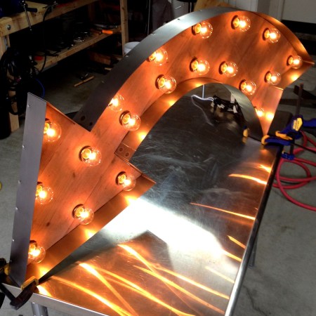
Fast forward to a few weeks ago. [Gnsart] happened upon the Arduino community. He realized that with an Arduino Uno and a commonly available relay board, he could finally build the sign. He started with some leftover cedar fence pickets. The pickets were glued up and then cut into an arrow shape. The holes for the lights were then laid out and drilled with a paddle bit. [Gnsart] wanted the wood to look a bit aged, so he created an ebonizing stain. 0000 steel wool, submerged and allowed to rust in vinegar for a few days, created a liquid which was perfect for the task. The solution is brushed on and removed just like stain, resulting in an aged wood. We’ve seen this technique used before with tea, stain, and other materials to achieve the desired effect.
[Gnsart] then built his edging. 22 gauge steel sheet metal was bent to fit the outline in a bending brake. The steel sheet was stapled to the wood, then spot welded to create one continuous piece. Finally, the light sockets were installed and wired up to the Arduino. [Gnsart] first experimented with mechanical relays, and while we love the sound, we’re not sure how long they’d last. He wisely decided to go with solid state relays for the final implementation. The result speaks for itself. LEDs are great – but there is just something about the warm glow of low-wattage incandescent lights.


I love this, relays aren’t a long term solution for this, but for people like us we’ll get enough clicks to satisfy ourselves.
nevermind, I didn’t see the SSR, this is a great solution. Sadly no clicks will be heard though.
I don’t get the distrust of mechanical relays. Sure, it’s an old technology, but it’s also very mature. Relays are often rated for millions of cycles, certainly longer than you’d see this sign in operation even if it were put into use.
Hmm.. many of the cheap relays (e.g. http://fi.farnell.com/multicomp/hrm2-s-dc9v/relay-pcb-spco-9vdc/dp/9480072 ) seem to be only rated for 100 000 cycles. Based on the video I would say each relay gets an average of 1 cycle per second.
So that would mean it is over spec after just 2 days..
That spec also calls for 100k cycles @ 16 amps. Those cycles are probably figured with the amount of (can’t think of the word, not corrosion but… yeah) created by the spark gap. At 40w, and the max of 6 bulbs, that’s only 2 amps of current. Enron math says it probably could last quite a bit longer ;)
Oxidation.
Ablation, erosion etc.
If you run AC rather than DC it’s less (much less) of a problem as the spark self-extinguishes, and the bulbs don’t care. (TFA doesn’t give details for that.)
A snubber (just a capacitor & relay) across the points will reduce or eliminate the spark as well.
Old tech relays would work fine for this.
I’ve seen old electromechanical pinball machines that are over a decade old and still running like new.
there is just something about the warm glow of low-wattage incandescent lights…. and that thing is extra power consumption, shorter operational life, longer on/off times and significant waste heat production.
And a look of quality, especially in the days of cheap Chinese blue LEDs everywhere. 3 lighters for a pound with an LED light on the end. A friggin blue one, the least visible colour. You can get yellow, or white LEDs, but apparently people want blue.
I think it goes back to the time in the early 1990s when blue LEDs cost more than a pound each, so you never saw them. One day they got cheap and became a novelty in electronics. The novelty wore off after 5 minutes but apparently the LED world hasn’t got that yet.
I’m also sick of rainbow LEDs gently pulsing through the spectrum. It was novel for those same 5 minutes, now it’s just cheesy. You can get RGB lightbulbs, but who uses any colour but white to see with?
Military flashlights often are red due to low visibility
That, and it doesn’t wreck your night vision as badly.
red is pretty high visibility actually (hence it being use for laser sights, warning beacons, Cats eyes in roads/lane markers corner posts, brake signals etc).
Rhodopsin is the chemical in the eye that is very light sensitive, – and gives humans “night vision” – hence why after standing outside for about an hour you can see very well. – try going out looking at the stars, after an hour turn on a flashlight and shine it in your eyes, then turn it off and see how long it takes to be able to see again.
Rhodopsin is “bleached” out by exposure to light, but it is least sensitive to relight…
(hence why military lights, starmap reading lights, and vehicle tail lights that you’ll look at for a long time whilst following at night are red).
red is used in flash lights because
RGB lightbulbs can have a large amount of use, from changing the temperature at night so that its easier to sleep, to increasing blue output in the morning or in work areas to help promote productivity and awakeness.
Red also distrupts your low light vision less, so when getting out of bed to goto the bathroom you’re not wide awake again.
In theory, couldn’t one develop a way to ramp LEDs on and off to simulate how an incandescent bulb would look, say, in an application that mounts the LEDs behind a translucent panel where one wouldn’t be able to tell the difference as readily?
That would give you the look of incandescents with the reliability, ease of control and and power consumption of LEDs.
Ask Jeri
http://www.youtube.com/watch?v=8X-W1S-fx8Q
How did these things originally work? I’m guessing they would not use relays due to the other comments pointing out that depending on relay quality, even with high quality signs in vegas running 24/7 would use relays pretty quickly I think.
There are ways to make relays last longer. One of them is to use mercury contacts (https://en.wikipedia.org/wiki/Mercury_relay).
Two words : Zero Crossing
When the load is switched “on” at the point of zero potential in the AC cycle, there is no inrush sparking that can fuse the relay contacts, thus prolonging the lifetime of a mechanical relay. Solid state (opto-isolated triac w/zero cross) switching would still be preferred in an application like this where switching occurs so frequently.
How can you do zero-crossing with relays? For one thing the timing would be really hard to get within 20ms, which is one cycle. Secondly how’d you detect the zero-crossing without using semiconductors, which we’re assuming don’t exist at the time?
Solid state zero crossing.
Solid state pretty much means semiconductors. Doesn’t apply to electromechanical stuff like relays, or valves / tubes.
A mechanical relay can certainly be controlled with a zero cross detector. While it can be done all analog with a comparator and a timer (555, RC, etc), a microcontroller throwing the relay just before the zero cross is my recommended approach.
It’s that repeatable? At 50Hz you have 20ms per cycle, 5ms between full voltage and zero. That’s not long for a relay to move, especially taking bounce into account. Seems a bit optimistic.
Not optimistic – very realistic. Mains in the US typically runs at 60Hz (16.667ms) not 20ms, so there’s even less margin for error than with 50Hz mains.
Try running 1-second on, 5-second off cycle tests with say a 5A load at 277VAC. Cycle one fixture with zero-cross detection and one without. The results speak for themselves. Mechanical contacts may weld in tens to hundreds of cycles with no zero cross. While relays thrown at (near) zero-cross last for hundreds of thousands of cycles (or more).
Switching at zero cross is simple and very effective.
Also, my comments aren’t addressing the availability of semiconducting technology at any earlier points in time. I was merely stating that the lifetime of mechanical relays can be significantly extended when being thrown at zero-crossings.
Yes, you can fire it at zero crossing or even a predetermined point, but
it is very hard to know the exact delay it would take as it is a
mechanical device. Sometime it would switch faster and sometime slower
and that changes over temperature and lifetime as it wears out.
When it switches, the contact bounces around a bit and takes time (which
is on the same order of magnitude as the AC period) to die out My
snubber solution would help with the bounces a bit.
Mechanical relay is not as simple as you think.
You could also have a snubber connect across the contacts. This would help to remove some of the arcing when the contacts bounces.
Flashing on and off in car indicators was often done with a bimetallic strip combined with a tiny heater, which was powered through the strip. It oscillated at a steady rate, and you connect the light bulbs to get their power through the strip too. It’s what made the little clicking noise in time with the lights, in old cars.
I’d bet a similar thing drove the old flashing lights, possibly through a relay.
If you made relays by hand and checked them well, you could probably get a lot more life, MTBF is the average including the bad ones! In Las Vegas economy isn’t really an issue when it comes to ludicrous displays of cash.
To follow myself up, failure’s not always an issue, like the early computers that’d blow a fuse every 15 minutes. So they designed them so the blown ones were easy to find and replace. You could do the same with a bank of relays, couple of minutes’ work replacing a stuck one with one kept handily nearby.
Those running electric-light notice boards, the ones that scrolled past news about World War II, had hundreds of relays and light bulbs, but they managed to keep them going for years.
Not fuse. Thermionic valve, or “tube”. Duh, pardon.
Still is.
The timing depends on how long it took the bimetallic strip to heap up, which depends on how many amps were flowing through it. More amps = more heat.
Now you have the situation where LED upgrade kits or bulb replacements need to have a resistor included merely to waste enough power so the amps flowing matches the old bulb – and keeps that old clicky blinker unit happy.
LED bulb with no resistor means very low amps meaning the bimetallic strip never heats up…
http://www.nationalsupplyonline.com/Mechanical_Border_Chasers.html
Why is everybody speculating? You’re on the internet.
Didn’t know what they were called! Anything on the ones with the scrolling text? The old pre-transistor ones?
The one in Times Square was called The “Motograph News Bulletin” or the “Zipper”. Here’s some links describing it:
http://www.wired.com/science/discoveries/news/2008/11/dayintech_1106
http://books.google.com/books?id=S1FfFwpp5Z4C&lpg=PT21&ots=A8YIrrdmtQ&dq=Motograph%20News%20Bulletin&pg=PT21#v=onepage&q&f=false
The google books link has some colour sketches but unfortunately I couldn’t find any pictures.
I remember seeing photos (I think in a really old “how it works” type book) of one similar to this except the letter cards had holes in them and floated on an energized pool of mercury. There was a grid of contacts above the pool that were directly connected to each bulb on the light strip, and the cards either allowed or blocked the contacts from touching the mercury as they passed between. Very hazardous, but virtually no contact wear or degradation.
Mechanical sign flashers use a motor driven cam to move heavy duty contacts. FMS and Signatrol are the two major makers of these units. You can still buy several models that have not changed in decades. They sell replacement parts to keep them going too.
I did something similar to this but made out of wood two years ago. Only difference is mine doesn’t actually light up contrary to what the photo shows on my website. I decided to just glue clear and frosted night light bulbs in the holes. Even broke a few for realism. The holiday lights took away from the realism in this case. http://www.newagainedm.blogspot.com
That is so retro-beautiful it brings tears to the eyes.
It makes me want to make a small version for my wall.
Yeah, solid state switching FTW on something like this, not that I don’t love me some relays because I surely do.
What about CD4017 + 555? Its not the same, but I’m just saying…
Nice build!
Yes indeed. I made one of these almost 25 years ago, very much pre the era of cheap ‘n’ easy microcontrollers. I went with 555, 4017 for the sequencer, diodes for the logic and transistors for switching the current, 12V DC bulbs for single rail simplicity and increased outdoor safety.
I believe originally these would have used something like a motorized box of cam operated switches.
To make the light bulbs last they should be pre-warmed with a low current so that the light bulbs are just glowing. If this is not done the filaments will burn out in a few days.
And it’s way easy to do – just shunt the relay contacts with a “keep-warm” resistor of a few ohms.
Well, more than a few ohms. 120VAC 15W bulbs are equivalent to 960 ohms when operating normally, so you probably want several kΩ here. Pretending I can extrapolate from a 1/2W bulb, 4kΩ 3W looks like a good starting place.
Keeping the bulb warm reduces inrush current, so it might even help with relay oxidization.
Yes, I neglected to mention both of those things. Thanks for the help. :-) Speaking of relays and stuff, I was a game repairman in the 1980’s, when video games were just catching on. An electronic tech/vidiot’s dream job! But one thing stood out in my mind – all the lamps on EM (electromechanical) pins (pinball machines) were driven with half-wave rectified AC, and switched with run-of-the-mill SCR’s, for whatever that’s worth.
For the never built movie prop a mechanical chaser could have been built by cutting a pattern out of a piece of sheet metal, mounting it to a disk of plywood, using some stiff bits of stranded wire for brush contacts then turning the disk with a small gear motor or surplus stage hand. With 12 volt power for everything it wouldn’t even need a safety cover. Wouldn’t have to last very long, many props for movies are lucky to last long enough to get through the production.
Grew up in the 50’s and 60’s , miss the real thing….