Are you guys tired of redesigned Arduinos yet? Usually we are, but [Ray] just released the SquareWear 2.0, and we have to admit, it’s a pretty slick design.
It’s an update to SquareWear 1.1 which we covered a year ago. That version made use of a 18F14K50 microcontroller, measured a tiny 1.6″ x 1.6″ and could easily be sewn into wearable circuits. But after receiving lots of requests to design a new Arduino based board, [Ray] obliged and made v2.0.
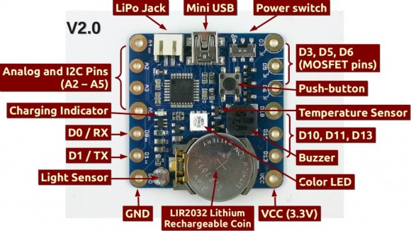
The new SquareWear is slightly bigger, measuring in at 1.7″ x 1.7″, but it packs a much bigger and more functional punch — just check out the image schematic above! The only catch is it doesn’t actually have a USB-to-serial chip on-board, which is why [Ray] was able to get the board so small and inexpensive. Instead it simulates USB in the software using the V-USB library. That method is much slower but still functional. To perform serial communication through the USB port it uses the onboard USBasp bootloader.
The board also features large through-holes to accommodate sew-able pin pads, making it super easy to integrate this into fabric!
For a complete explanation of the SquareWear 2.0, check out the video after the break.


I still don’t like the idea of having the temperature sensor right next to a heat source (LED)…
since it’s a “wearable”, what are the consequences of putting the temperature sensor right next to a human heat source?
A single LED isn’t going to produce nearly enough heat to produce a noticeable difference in temperature in the area. Especially if it’s used as a wearable, at which point temperature accuracy pretty much goes out the window.
That is not a normal single LED. It’s a high power RGB. It heats up easily and the heat dissipation goes through the PCB and directly under the temperature sensor.
Lars has a very good point.
He should use a WS2812 LED with 1 I/O.
That’s only an issue if you are turning on LED full brightness AND measure temperature at the same time. You can turn off the LED, or dim it when measuring temperature.
How does WS2812 solve the problem? It dissipates more power and is like 5x more expensive.
Check the video @8:00 he measure temperature then change the color of the LED accordingly. So he turns LED AND measure temperature :P hehe
The WS2812 comment was not related to our discussion about temperature. It was a general comment regarding his design to save precious I/O pins.
Well, you can still turn off the LED when taking temperature measurement, then turn if back on. It only takes a few milliseconds to get an analog reading, so the LED will look like it’s continuously on. Also, as I said, you can always use PWM to dim the LED. At 3-5mA the LED will look sufficiently bright, and will not dissipate much heat at all. At any rate, the drift caused by the LED is probably not much more than the error / accuracy of the temperature sensor anyways.
For 99% of cases it’s gonna be “98.6” anyway. A human body should generate more heat than an LED, and I doubt the LED would need to run bright for it’s purpose. When it’s on at all. Which won’t be often on a watch battery.
How come these wearable designs never have worthwhile ESD protection? I’d think if any board is going to get zapped, it’s one that’s attached to the front of a constantly moving piece of cloth. Has anyone had such problems with a wearable design, or am I worried about a nonissue?
ESD is both less and more of a concern in wearables simply by the high path loss in conductive threads but made more concerning by the same threads needing “more gain ” etc.
MY suggested “Best Practices” always have involved Optoisolaton or potted transformers etc outside of intrinsically protected things. Protection is a “pays for itself” expense category.
Yeah- you may “get away wit it” x times… but the cost of prevention Vs replacement is likely a no brainer over time.
“pays for itself” is a pretty fuzzy concept when it comes to fashion and style
it may “pay for itself” in a single use if that use is on a fashion runway
Optoisolators don’t protect you from ESD, you need special ESD devices for that.
My suggestion is to only use it with cotton fabrics and don’t ever stop dancing (so you’re always a bit damp).
PS: I didn’t want to like this board (yet another overpriced Arduino variant, yawn!) but I do, especially the built-in battery charger system. It totally *destroys* the Lilypad (and for the same price as just the Lilypad main board with no accessories!)
Optoisolation sounds nice, it may help you at a few kV, but you’ll need
much more than that to survive the higher voltages for ESD.
http://www.edn.com/design/test-and-measurement/4368466/Understanding-and-comparing-the-differences-in-ESD-testing
>Values for the high-voltage supply range, according to the test level, from 0.5 to 15 kV.
>IEC61000-4-2 air gap: +/- 15kV
>IEC61000-4-2 contact: +/- 8kV
Hate to say this, it doesn’t take a whole lot of experience to “design” (like copy/paste)
an “Arduino” board. It take far less than understand ESD protection and
how it affects layout and and not simply springle “ESD protection” parts
on the board.
I meant far more…
There is always static guard or ESD bags. :)
By “Optoisolation” in this context – there’s a realistic threat assessment to evaluate. One could for example have photosensors on the “expensive” board and a “cheap” board as the at more risk one. Clamp Diodes and ancient yet still valid tech hacks such as gas tubes- often a Neon Lamp is Quite Good Enough to damage control those MOV’s in a layered ESD defense plan.
in a >$300 device one commonly can see stupidly LITTLE attention spent on protection.
Seeing near zero design for ESD in an LED point boards coupled by Crofon plastic fiber etc.
Small board has an LED Driver and battery for Driver so IR/visible gets fibered to sensor on the “expensive” board.
WHy would i want to use over priced controller like this?
If you think it’s over-priced consider the other angle: When you need to build a wearable in your own workshop this serves as a reference design because it’s open source.
At $22 you think it’s overpriced?. Similar products like Lilypad and Flora are both priced at $25 and they don’t have nearly as many built-in components.
That was my first thought, too, but take another look…if you’re building the sort of thing this is aimed at then it will be FAR cheaper than buying all the parts (and much easier because it’s all on one PCB).
This is a great board, I got it last year…
i did not know they made a rechargeable coin cell.
It makes me crazy that all coin cells aren’t rechargeable. Yesterday I was just playing with the Open Hardware Summit badge from 2013 (I didn’t attend so thanks [Andy] for sending me yours!). The source code for the badge states very clearly that the coin cell is good for about 100 page turns…. then? Well, then you throw it away. This is crazy to me.
I’m sure that some are. Those CR2032’s aren’t rechargeable, but the LR2032 (or even LIR2032) are, but at lower capacities.
So someone want to tell me the difference between this and a lilypad?
Check the SquareWear homepage: http://sqrwear.com, there is a table comparing it with Lilypad and Flora.
Mhm i like that it’s based on the 328 chip, but the onboard sensors are kind of…strange… often you want to hide the module completely so the light sensor is sort of odd.Temperature may be semi useful for sensing ambient body heat and the LED is…weird.
It’s a nice board though.
If you need certain sensors, like light sensor, to be separated from the board, you can always connect extra sensors to the available pins. The on-board components are useful for learning and beginners, allowing them to dive in and focus on the programming part.
What is with this and the audrino both having nonstandard pin spacing?
Oh, hey, you’re right, the larger pads are misaligned :S
Maybe it’s so that people don’t stick non-compatible stuff into it?
What is standard pin spacing? You mean 0.1″ like a breadboard? This board is never intended to be used on a breadboard. Also the the large pads are designed so you can solder sew-on snaps. They are much larger than 0.1″ pin spacing.
It’s designed for *sewing*, not breadboarding….
I have no idea why this uses this fake USB hack with V-USB instead of using the proper AVR chip in the first place. That being the ATmega32u4 as found in the Leonardo. It’s SMD, and has real USB built in.
ATmega328 is half the price of ATmega32u4, and is more compact. If V-USB works, what’s wrong with this fake USB hack?
My comments on ESD were and are for advocating we always raise the bar. NOT to disrespect the Featured device!
Calling an emulation “Fake” in what might be viewed as deprecating the method is amusingly elitist. The reason I bothered commenting now- on the needless disrespect of Ray’s excellent V-USB usage…
Good Enough- Is.
anybody else having corrupted files problem after downloading from github?
You should not use ‘Save Link as’ or ‘Save File as’ when downloading a file from Github. Either download the entire repository as a zip, or use the ‘Raw’ link to download an individual file.