Trying to reinvent the clock has been done over and over again, but it’s always fun to see how over-engineered and complex these designs can get. [Bertho’s] last working clock in his house was the built-in clock on the VCR, so he decided it was finally time to build his own 504 Segment clock.
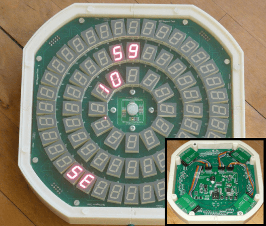
Yep, that’s right, 504 Segments! This clock uses 72 7-Segment displays to tell time. The video after the break shows the clock in action, but time is read by looking at each ring of displays: outer=seconds, middle=minutes, and inner=hour. [Bertho] could’ve just stopped there, but he decided to load the display up with sensors, so hand-waiving can change modes, and brightness can be regulated based on ambient light conditions. And since he has individual control over each segment, he has implemented some pretty cool mind-melting animations. Oh, and did we mention that the display synchronizes with an NTP server?
The display is divided into 4 quadrants, each containing 18 7-Segment displays. The control architecture is interesting because each quadrant is controlled by its own PIC microcontroller, which handles the continuous multiplexing and modulation of the 18 7-Segment displays. A main control board contains another (more powerful) PIC to update the 4 quadrants via a serial bus. This board also handles the Ethernet connection, sensor interface, and local RTC(real time clock). This isn’t the first time we’ve seen [Bertho’s] amazing work, so make sure you check out his useless machine and executive decision maker.


Is it trying to say 53 seconds in the banner image? :o
Dude. 35.
SE, short for Seconds.
Hour, Minutes, Seconds.
10:59:35 AM
PCB routing massacre…. though one could just throw 36 SCT2024 for less than ~15EUR at it, drive everything statically and then a very small MCU could handle it (without NTP of course).
Actually, having to route 9 chips on there is more complicated than the one PIC and 30 small row/col drivers. It would be easier to drive/control when using six TLC5947 or equivalent.
Very nice. Watching the video and the ‘wavy’ patterns it can produce, perhaps adding a microphone and some processing could turn the display into a cool wall-mounted graphic equalizer when music is played in the room.
I had been pondering the idea of making my own 7-segment displays with RGB leds. However, the CPU requirements are then a bit more steep and were not a real option when I got the original idea. It is also a nightmare to route the tripled complexity.
I have been considering redesigning both the quadrants and the main control board with ARM controllers. Especially the control board CPU is rather busy when handling Ethernet and the PIC cannot do 10/100 but only 10Mb. However, using ARM means an external Ethernet PHY. OTOH, I’m starting to see the limits of the PIC both RAM and FLASH are getting stretched (still missing IPv6 and that will probably not fit), which an ARM solves quite easily.
Put it on Kickstarter and I’ll buy one. (c:
Nope. The audience IS there, but you don’t need a business to support it. Make it a kit, and get Sparkfun or one of the other open-source resellers to take care of the sales. Kickstarter /should/ be for people who want to create a business around their product. I’ve seen enough projects on Kickstarter, ones that HUGELY exceed their funding goals, that should not have been there in the first place. Building a business around a product is great if the economies of scale will work to make it a product in its own right. But if your product is a niche (geek niche in this example) product, it would be better to hire it built overseas, and sell it somewhere like Thinkgeek.com, or turn your Gerbers and BOM to Sparkfun, and have them handle the business hassles (Sell your widget: option 2).
If I ever produced something this cool, that is what I would probably do. Especially if I built it for myself, and not with the intension of “productizing” the thing.
And yes, if I had the money to spend on something like this, I would definately buy one if it were available.
Sound business advice…
thank you.
I *think* you can buy RGB 7-segment LEDs, altho gods know where they fit all the pins. Just looked, they do! Bet they aren’t too cheap.
From Adafruit (http://www.adafruit.com/products/1399), that would amount to about $1000 for the 72 displays alone. They are also about twice as large (1″ vs. 0.52″) and that would make the whole clock also twice as large.
I do not think that this is a viable option…
True, but that is adafruit. No doubt you coukd get those for a tiny fraction of that cost.
Cool clock! I like the effects, and I like that it is unique but still quite useable.
I have an idea that I think would look neat and make it more readable… You could show the numbers at the top of their rings, and have a line of dashes (or an undulating wave, or whatever) following the numbers up to where the hands would be, so you’d have the numbers all lined up, with arc segments to show time the analog way. Alternately, you could put the numbers on the moving ends of the arc segments. Not as easy to read, but still neat looking.
Thanks.
The neat thing about the clock is that you can send your own version/design over Ethernet. The video shows “handles” at 2:09, which are coming from my laptop.
I liked the combination of a round clock with numbers running around. It seems hard to read, but it only takes a couple of hours (maybe a day) to get used to and then you know how to read it instinctively.
Very cool clock. Probably one of the biggest and hardest cocks I’ve ever seen. Clearly a lot of effort went into making this perform as well as it does.
I bet you regret that typo….
I wonder if he implemented a feature that would make a ding dong?
I specifically opted _not_ to have a buzzer in the design… Fairly good decision, considering the type ;-)
I reported that comment. It’s very obscene.
Must be a grower
“I reported that comment. It’s very obscene.”
I considered cuntacting a moderator as well, but in the end I decided againstit.
Hm, when Berto gets going he doesn’t mess about!
I was a little disappointed when I saw it didn’t have 13 on the inner ring, and 61 on the two outer rings. Then you can advance each ring 1 display each step, and the actual pointer is between the two digits (prepending single digits with 0, though not necessarily displaying the 0).
There are several reasons. You cannot have two rings with the same number of displays of same size and still have them fit tightly. Using 135 displays instead of 72 is quite a step-up in cost. Using 60 (or 61) displays in a ring makes the diameter substantially larger and that would not fit on four times 10x10cm PCB (one for each quadrant). Using more displays would require more IO-pins or external buffers/demultiplexing; each adding to complexity and cost. The current design is already a very tight fit.
However, if you want differently, you are welcome to adjust the design and build your own version ;-)
Didn’t mean to try to offend, I was only a little disappointed. It’s still quite an impressive project :)
None taken, just explaining… :-)
All I can see when I look at this is the packaging for certain birth control pills.
This is awesome. :D
Awesome. I really like the pattern mode too.
IMHO, I think it would look a little better with a tinted plastic on the front. But that is nothing to complain about. I even like the rainbow ribbon cables. It just adds to the Retro of the 7 segments.
I’ve been looking into a tinted front to make it really red, just like old clocks. However, the light sensor is impacted quite severely when you tint the front. One could, of course, use a lesser red or other tint, but that is not “real” anymore ;-) Therefore I opted to go for white soldermask on the new PCB to make it all shades of gray.
There is also a hole in the middle to stick the movement sensor through because Plexiglas does not transmit 5..7.5um wavelength heat signatures. But a hole would not work “nicely” with the light sensor.
I like it alot, but I’d rather it had 30 segments in the outer ring – the sometimes 2, sometimes 1 second jumps bothered me, even though should not matter. I wonder if there was a specific reason to this choice, or if it was simply the greatest density of 7 segment displays that fit?
Two reasons: 1) 30 in the outer ring cannot be divided by 4, so it can not be done in quadrants; 2) 30 displays tighten the circle too much so that it does no longer fit around the middle circle without adding space between the displays.
The choice of 3, 6, 9 for the quadrants was the best combination to have about evenly spaced circles and all displays tightly packed.
The “hopping” of the seconds is a strange thing, yes, but that will no longer bother after a while once you see that there is a very regular pattern. More people have said the same thing until I asked them to find the patterns. When they did, the irritation was gone.
504 ERROR!