Have you ever found the need to measure the capacitance of a capacitor? No multimeter handy (for shame)? Well, as it turns out you can actually measure capacitance using your Arduino Uno, with no external components, and only ~20 lines of code.
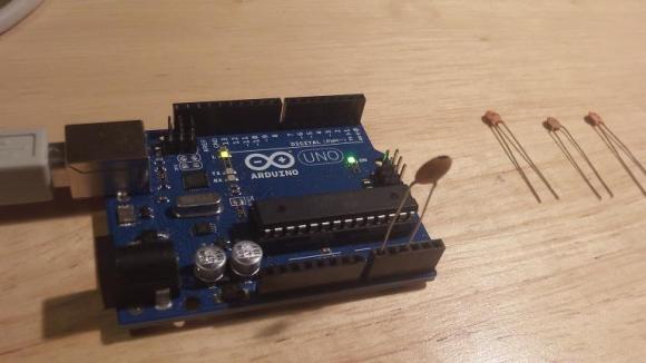
[Jonathan Nethercott] does an excellent job explaining a capacitance test circuit which uses a reference capacitor to calculate the unknown capacitance. He further explains that, with the Arduino Uno, you can remove the reference capacitor from the circuit, and simply use the stray capacitance present in the board and microcontroller, which can be calculated. This results in the test circuit being as simple as plugging in your capacitor to pins A0 and A2.The code is quite simple: it sends a 5V pulse to the capacitor and measures the voltage on the other side, looping every half second, and outputting the data onto a chart.
It does, however, require calibration. [Jonathan] measured a known capacitor for a baseline, and used that data to calculate the stray capacitance in the Arduino. Once calibrated, he found that you can easily achieve a resolution of about 1% for capacitors between 3.5pF and 225pF, and around 5% for capacitors between 0.5pF and 1300pF — you can see the results of his analysis here. He plans on determining the accuracy and linearity too, but he will need some very accurate reference capacitors.


Formidable
Agreed, I’m quite impressed by this. Good use of an uno, and I’d think a good first step into some coding for people who are beginning to tinker with electronics.
I might do something like this with my scouts.
if you don’t immediately try this with an arduino you have on your desk after seeing this writeup, i’m surprised
I won’t. I have a proper meter with capacitance measurement.
So do I, but I’m going to try it anyway. Just for fun.
Possibly one could attach one of those tiny Arduinos right onto a pair of those cheap SMT tweezers? What about stray capacitance from the user’s hand, etc. ??? Could be very nice.
I was exactly thinking of that. The CapSense library on Arduino on which I’m working for two days (not enough precise for me) works the same way than this script (sort of…) but uses digital pins.
Know I want to try with this new script ;)
You can use the internal pullup to charge a cap and time it.
Should work for larger caps when this method peters out.
I think the internal pullup is about 30k, so yes that should work for capacitors between a few nF and a few uF. Getting a range of less than 1pF to more than 10uF with no external components would be pretty cool. I’ll give that a go when I get a chance… Thanks.
The optimum lies in the 10-100pF range … which means you can use this technique to measure capacitive humidity sensors directly. You could even make them on the PCB as traces without solder resist.
Minor suggestions for larger capacitors:
– it might be better to sample until a certain threshold charge has been met and use the time constant to calc the capacitance.
– alternatively, you could sample 16 values in a loop, fit the ideal curve and extract the C value. This should improve the resolution.
Should be easy to add a range switch.
Or, you can make it test (nearly) anything:
http://forum.arduino.cc/index.php?topic=164112.0
Note that the above (as it notes in the comments) is a port of this project (originally done using an ATMega8, if I read it correctly):
http://www.mikrocontroller.net/articles/AVR-Transistortester
If you are lazy, you can go on Ebay and find this tester being sold all over the place from Shenzhen vendors…
Does anybody know how to do this for inductance? I have a Sparkfun capacitance meter which is based on a PIC and I would imagine probably works similarly to this Arduino solution. I can’t seem to find an inexpensive inductance meter that actually works though.
Look for a (insert unknown brand name here) 4070L. They can be had cheaply from Amazon and Ebay, and will measure from about 50 uH to over 10 H, in theory. In practice it does a decent job on medium size inductors but isn’t precise enough to measure the really small stuff. It also measures resistance, capacitance, and includes a transistor checker. Currently $15 on Amazon:
http://www.amazon.com/Hiyadeal-Inductance-Capacitance-Resistance-Meter/dp/B008QKJOCQ/ref=sr_1_3?ie=UTF8&qid=1390494536&sr=8-3&keywords=lcr+meter
The meter mentioned starts at mH though? These things are useless.
So what happens when that 100uf cap has a 20v charge on it? That can’t be too good for the arduino.
Always short the caps first, simple enough. It’s the same thing you should do with any other capacitance tester.
No, it would not do the Arduino any good, but it would likely increase Arduino sales by one.
Where’s the like button? ;)
To elaborate, the total amount of energy in this case is C*U*U/2 = 0.0001*20*20/2 = 20 mJoule. Doesn’t sound like a big deal but this energy is delivered in a very small window of time and is dumped on relatively small microelectronics structures.
The energy is dissipated by the ESD protection diodes, they redirect the current to VCC and limit the input logic to VCC+0.6.
The behavior of protection devices is characterized in TLP (Transmission Line Pulsing) measurements and qualified in MM (Machine Model), HBM (Human Body Model) and CDM (Charged Device Model) tests that subject the device to a standardized setup that mimics real-world scenarios. For AVR you can find some numbers here:
http://www.atmel.com/images/doc1619.pdf
http://d1.ourdev.cn/bbs_upload782111/files_1/armok0117484.pdf
Hooking up a charged cap like in this scenario bears close resemblance to two kind of tests: an MM test and a surge immunity test. The transient in our case will be in the ~µsecond or even 10µsec range – an order of magnitude longer than MM and as such worse. ATmega8 can suppress up to 400 in MM, which boils down to a whopping 16µJoule of energy per pulse. From whatever I can find on the internet they also test for Fast Transient Burst – bundles of 75 pulses totaling in the area of ~10mJ over a 15 ms dissipation time. The prolonged dissipation time (there are pauses between the pulses) is something that renders it incomparable to this question. Surge immunity tests are only done on power supply lines, not IO, so I can’t translate to this case.
All tests you’ll find that qualify the IO lines wrt to pulsed overvoltage abuse are at least 1 order of magnitude lower than the scenario we’re dealing with here. And those are upper limits or limited to power supply. So yes, the input protection will go poof. It’s quite possible, though, that the damage will be restricted to the protection diodes and the logic will continue to function until the next minor pulse comes along (e.g. when you remove the cap and touch the wires).
So where d do you get a precision cap for calibration?
Type “reference capacitor” into the Search bar at *bay…
this is my first time i’ll by a microcontroller (arduino uno) and i’m a beginner.Please, would you mind telling me is good or not for me this arduino
can arduino be used as a Measurment device for NFC devices?