We love the WS28xx projects because even if we never plan to use them, the signal timing is like the most addictive puzzle game ever. For instance, check out this WS2811A driver which uses hardware SPI to generate the signals.
The WS28xx offerings place a microcontroller inside an RGB LED, allowing them to be individually addressed in very long chains or large matrices (still a chain but different layout). But the timing scheme used to address them doesn’t play well with traditionally available microcontroller peripherals. [Brett] had been intrigued by some of the attempts to bend hardware SPI to the will of the WS2811 — notably [Cunning_Fellow’s] work featured in this post. He took it a great step forward by simplifying the driver to just one transistor, three resistors, and a capacitor.
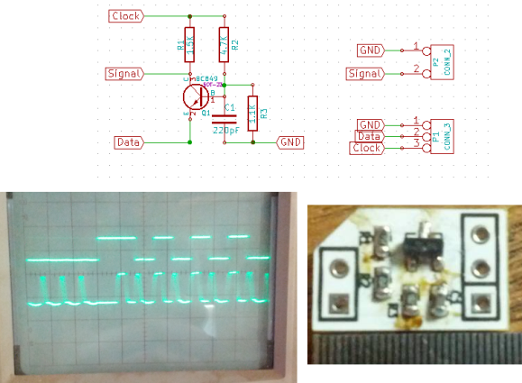
Click through the link above for his step-by-step description of how the circuit works (it’s not worth re-explaining here as he does a very concise job himself). The oscilloscope above shows the SPI signal on top and the resulting timing signal below. You will notice the edges aren’t very clean, which requires the first pixel to be very close to the driver or risk further degradation. But, since the WS28xx drivers feature a repeater which cleans up signals like this, it’s smooth sailing after the first pixel.


Is this a bi-phase encode protocol?
The DHT11 temperature/humidity sensor has a similar variable pulse width protocol, except it’s the sender and the microcontroller is the receiver. I had an idea to use a UART and a bit check, but ended up reverting to the more usual timer capture as the UARTs ended up being used for other stuff.
His idea is ingenious. i can’t think of any way to make it any simpler.
You could make the timing more precise with a 74HC221 (Dual non-retriggerable monostable multivibrator). This beauty has 3 trigger so that you can make it trigger on the clock output and select the monoflop based on the level of the data output. But you must calibrate the pulswidth with an oscilloscope.
But again way more complicated than his solution, just use an ws2812 to retime your signal..
@cyberteque: No its kind of a pulswidth protocoll. The frequeny is 800kHz. A low level equals 28% and the high level is 87%.
I really like these LEDs. They are great even for panel indicators for your projects(just 1 pin to drive them all…. if only there was a 5mm through hole version of them….
My favorite driver is the one here, which can do anything from bit banging to PWM+DMA. https://www.mikrocontroller.net/attachment/168672/ws2812.zip (why can’t i find the topic relating to it?)
Maybe the WS2811 is different, but both the WS2803 and WS2812 are entirely compatible with standard hardware SPI, using CPOL0 / CPHA0 / MSB, at basically whatever clock speed you can push over the wires.
Nice Idea,
I went the SPI route, with a lookup table of bit patterns. Packing 4 bits of WS2812 data into each spi transfer. Have a write and code here : http://www.soldersplash.co.uk/2013/12/christmas-tree-dipcortex-ws2812b/