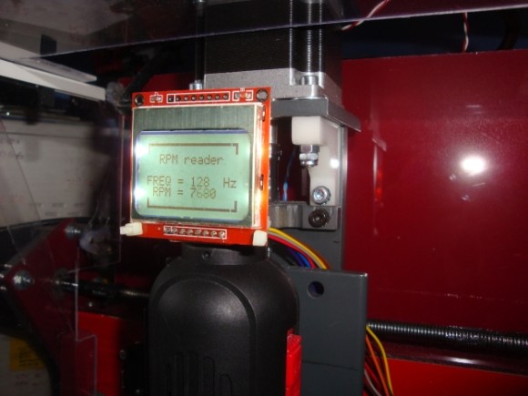
[Rui] recently put the finishing touches on his homemade CNC mill, which utilizes a dremel-like rotary tool. The problem with using rotary tools for this kind of application is you don’t really have an accurate speed readout… so he designed his own RPM gauge.
The sensor is in itself very simple. He’s using a TLE4935L hall effect sensor, a spare 16FE88 microcontroller, a Nokia LCD, and one tiny neodymium magnet. The magnet has been carefully epoxied onto the motor fan, with the hall effect sensor close by. He’s also built a guard around it, just in case the magnet decides to fly off at high speeds.
During testing he hooked up the hall effect sensor to both his home-made circuit, and an oscilloscope to confirm his findings. Once he was assured everything was working properly he sealed it off and mounted the LCD above the spindle as a nice digital readout.
This isn’t [Rui’s] first project to grace the front page either — he’s also made a great laser range finder hack as well as a laser trip wire for Airsoft games!


I did the same thing a few weeks ago with my drill press, also using a hall effect sensor, but was just too lazy to make a video and submit it :/ Guess now it will seem like a copy-cat, damnit.
Submit it, I love seeing the same thing done several times slightly differently. Most of every hack here has already been posted more than several times. Please give us another one, tell us why you did it, what you learned, what you might do different. Maybe your code is different?
It is a cool hack. Another thing to do with these cheap dremel-oid spindels, is to hack the speed control so it can also be set in the gcode, not by hoping you will set it correctly.
Usually these speed controls work by using a potmeter that determines how fast a capacitor charges. Once a voltage level is reached a triac is triggered that supplies the next phase to the motor. You can bypass the potmeter with an optocoupler and a small resistor. You do need the opto because the whole circuit is at mains voltage (120 or 240V). Now drive the opto with a PWM freqency that is significantly higher than the net and you got yourself a cheap dremeloid with CNC speed control. For a bonus you could use this speed measurement to make a feedback loop to up the power when the spindle gets more load.
Then you may wonder how long before you will invest in a more powerful and more precise spindle motor.
I was concerned at first with the magnet unbalancing the fan and causing bearing wear or other problems. Then I RTFA and saw that A) These are TINY magnets, and B) There are two – on opposite sides.
Nicely done, and bilingual as well!
Why not paint white marker on one blade and read it optically? Or just light unmodified fan by LED and divide counted pulses by number of blades? I don’t think that sensor in air exhaust has any chance to be dusted enough to render it useless. Most of fans and blowers have odd number of blades so it is hard to rebalance it after adding element with different density than rest of rotor.