[Josh] had a little project where he needed to keep a variable in RAM while a microcontroller was disconnected from a power source. Yes, the EEPROM on board would be able to store a variable without power, but that means writing to the EEPROM a lot, killing the lifetime of the chip. He found an ATTiny can keep the RAM alive for a variable amount of time – somewhere between 150ms and 10 minutes. Wanting to understand this variability, he decided to solve the mystery of the zombie RAM.
The first experiment involved writing a little bit of code for an ATTiny4313 that looked for a value in RAM on power up and light up a LED if it saw the right value. The test circuit consisted of a simple switch connected to the power pin. Initial tests were astonishing; the ATTiny could hold a value in RAM for up to 10 minutes without power.
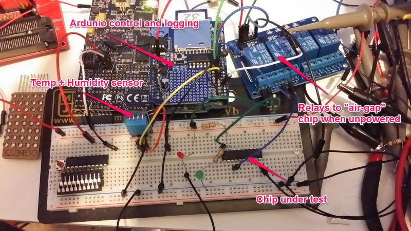
With the experiment a success, [Josh] updated his project to use this new EEPROM-saving technique. Only this time, it didn’t work. The value hidden away in RAM would die in a matter of milliseconds, not minutes. After tearing his hair out looking for something different, [Josh] rigged up an Arduino based test circuit with humidity and temperature sensors to see if that had any effect. It didn’t, and the zombie RAM was still not-undead.
The key insight into how the RAM in an ATtiny could stay alive for so long came when [Josh] noticed his test circuit had a LED, but the actual project didn’t. Apparently this LED was functioning as a very tiny solar cell, generating a tiny bit of current that kept the RAM alive. A dark room with a flashlight confirmed this hypothesis, and once [Josh] gets his uCurrent from Kickstarter he’ll know exactly how much current this LED is supplying.


That’s cool
I experimented with an LED as a solar panel before.. Well, more as a sensor. The voltage should change depending on how much light it can see. A laser pointer or LED of the same color shining into it will induce more voltage than one of a different color. I’ve tested this with a red and a green LED and a red laser pointer. I originally had the idea when trying to understand an old hackaday article about an input device that was an LED matrix that would output a pulse of light then switch LEDs to input and sense it. I can’t find the article now.. it’s probably at least 5 years ago.
I’ve used this technique in this project: http://github.com/Miceuz/PlantWateringAlarm essentially you briefly charge the capacitance in led while reverse biased, and then the light falling into junction discharges it. By measuring time it takes to discharge you can determine the amount of light.
You mean this one? http://hackaday.com/2006/02/21/low-cost-sensing-and-communication-with-an-led/
An interesting bit of serendipity. I have used LEDs as photosensors before, but never seen one actually power a circuit before.
Fascinating!
I tested EEPROM endurance on ATTINY devices a while ago. While they’re promising 100,000 writes, I routinely got 4-5 million cycles before one-bit errors.
If you keep the µC in a nice environment they go much further than advertised. Add in a bit of code to reuse cycle through the entire EEPROM map and endurance ceases to be a factor.
(assuming byte-addressable and storing 32-bit data)
have 0x0 store jump value — addr
0x4 + 0x8*n — count[n]
0x8 + 0x8*n — data[n]
To store data:
if (count[addr] > 50,000) {addr++; count[addr]=0}
store data to data[addr]
Now you can write data 2500000000 times before any one address has been written more than 50,000 times. If you only write one time per second, that means I will probably be dead before your EEPROM is.
I reserve the right to being completely wrong with above code/statement
that is what wear leveling is about, spreading, the writes out by moving things around.
The problem is when you write the same location repeatedly
Depends on the size of the EEPROM and the write frequency. Also, instead of storing a write count in the EEPROM, one can instead use a single-byte marker to indicate the head of a cyclic buffer; that byte flips value each time the whole buffer has been written to. When the µC wakes up, it reads the entire EEPROM to find this head (first indicator that is not equal to the one at position 0). When it’s time to write: if(++pos==records) { pos=0; indicator^=0xff);} and then writechunk(pos);
That way you can store a structure of arbitrary length at a different position in the eeprom map every time, wasting only a single byte for each record. It’s better than storing a count at a specific spot (and have that spot fail first).
Assuming a tiny ATTINY with 128 bytes of EEPROM and a chunk of 4 bytes(including indicator) and a write frequency of 1 per second, that’s a full cycle every 32 seconds.
If we use the datasheet’s pessimistic endurance of 100,000 cycles, that’s 32*100,000=3200000 seconds, only a bit more than 37 days.
I sincerely hope you’ll live longer than that.
50,000 writes per address * 50,000 address increments, at 1 address write per second = about 79 years. I doubt the EEPROM is rated for more than 20 years.
The attiny4313 referred in this article has 256 bytes of EEPROM, not 50K.
Also, writing a single address (one byte) is useless. You can’t differentiate that byte from any other in the EEPROM map on power-up, so you need to store more, either a write counter or a head-of-cyclic-buffer indicator. In the simplest case scenario a single byte of data and a byte for head indication gives you 128 different spots to write your data, so 12,800,000 writes, and that’s about 148 days at 1 write/second.
So where do you write your write index?
Inside the stack, itself. Assuming you’re dealing with memory where it is 1 when erased, you just check for the first byte unequal to -1 (0xFF). This of course requires that you never, ever use 0xFF as a valid value for items on the stack.
With enough space available you can write it anywhere you wish, if you treat it as a marker and not a pointer. Need to write something? Just write a struct of your something with the first byte/word/long etc. being a counter that autoincrements, next time you scan the memory for the same struct with the highest first byte/word/long to find the latest value so that when you need to write just advance the pointer to the next struct (if available). A bit clumsy, not elegant and surely more time consuming, but on small devices (which get overwritten the most) you do exactly one write per write cycle, no need to index, set or clear anything.
If the data you write is fixed-length (e.g. a C struct) and you are interested in the most recent state (e.g. persisting state across power cycles), a simple wear-leveling approach I’ve used is to set aside an initial n bytes for management, proportional to the total memory and data size. EEPROM/FLASH bits can be cleared (1 to 0) without incurring an erase cycle (wearing out the memory), and can be cleared bitwise on many micros. All bits start out at 1 after an erase.
Say the remaining memory can store n instances of the persistence data structure (ideally you set aside close to n bits, or ceil(n/8) bytes, for management). Each time you write an update, scan through the management area until you find the first “1” and write the data at offset (x*sizeof(data)) in the data area, where x is the bit offset of the first 1 encountered. Then clear the next bit in the management area. When there are no more 1s left in the management area, perform an erase cycle and start over. The system then can always find the freshest copy, but wear on each bit is reduced by a factor of (number of struct copies that will fit) and distributed evenly across the memory.
The “search loop to find the first 1 in the management area” approach may sound crude, but this search is very fast, and on typical micros where the EEPROM is measured in kB, does not consume much power either. I used this approach on a vibration-powered (piezo energy harvesting) sensor node that transmitted wireless packets; the energy consumed by the search was negligible compared to firing off an RF packet.
great work !!
How long does the ram last if a capacitor is soldered across vcc and ground?
Depends on the size of the capacitor but you could run the whole micro for a while on a big enough supercapacitor.
I think, though, that the LED would work better because with a capacitor you will probably end up with enough voltage to power on more parts of the circuit, which will draw more current and shorten the effect by a lot.
If it were external RAM, maybe, or if you rigged up a really efficient voltage converter to drop it down to the right value. Also, capacitor leakage would probably be a problem…
Maybe power it off AM radio?
possible to use a tiny coin cell instead?
This whole idea has been handled by various NVRAM solutions. They have chips dedicated solely to RAM power management.
That is a very cool bit of information and props to the guy to finding an explanation to this mystery.
A very fascinating discovery. I saw an article here way back that talked about using display pixels as a camera, but to think that an LED could power a circuit, even in the smallest amount, is truly interesting. I’m curious if circuits that require saving a variable during a reset could utilize a capacitor to drive an LED with another LED feeding the RAM some current or if the presence of a capacitor need be the only requirement. My knowledge of electrical circuits is limited in this area.
The STM32s (at least the ones I’ve used so far) don’t have EEPROM, but you can write to the flash space. There is a cool “EEPROM Emulation Library” that works well. [PDF] http://www.st.com/st-web-ui/static/active/en/resource/technical/document/application_note/CD00165693.pdf
One interesting thing is that it has to deal with the peculiarities of Flash memory (you can set bits whenever you want, but you can only clear them a while page at a time…. I think. That’s off the top of my head) so what the library does is keep two pages reserved, you can keep writing anything you want to a few virtual eeprom spaces, when it runs out of space on one page, it copies the most recent values to the other page and clears the first page.
Here’s what I’m getting to: It is able to spread writes over a larger number of memory locations. So if you only needed to save a few values EEPROM, you could use a similar method to spead the wear out over say 10x or more spaces, increasing the useful lifespan of the memory by a lot.
Maybe. Not sure it is would be possible to do it the same way, now that I think about it…
Just a thought.
STM32s (all? not sure. F103 certainly) have some backup registers that are battery backed SRAM, powered through VBAT like the RTC. On ones ive used there’s 84B, which isn’t a lot, but is useful for storing some configuration values and whatnot.
Of course it only works if you have a battery on VBAT pin.
Wow. I’ve wondered about why the ram sometimes stays alive. I’ve used LEDs to sense light too.
some of the learning remotes use the transmitting LED as a sensor when they learn
http://hackaday.com/2012/07/27/writing-on-leds-with-a-laser-pointer/
Doh… completely missed this one, thanks for posting. I envision giant screens where passers by can write using lasers.
Wouldn’t a supercapacitor and use of the chip’s low-power modes be a more reproducible way to accomplish this? The ARMs I’ve worked on have <1uA low power modes that retain partial RAM contents.
This is fascinating!
I think he needs MSP430FR5969 http://www.ti.com/product/msp430fr5969?DCMP=wolverine&HQS=wolverine-b
I wonder if he could write the same value to several blocks of ram and use a statistical technique to recover the memory if only a few of them are corrupted – it might be that the group performance is good enough if ram cell failure is sufficiently uncorrelated.
Sure when you add redundancy you increase what you can recover, use error correction codes, that what they are designed for ;)
Make sure you figure that into your power budget.
But calculations on power-on shouldn’t matter, and I don’t see how extra writes to RAM will cost extra, given that they’ll have some garbage in them anyway.
Would writing zeros to everything else lengthen it, though?
If you want to play with Zombie RAM on larger systems, you may want to play with Cold Boot Attack. ( http://en.wikipedia.org/wiki/Cold_boot_attack )
or
You could try your $7 can of compressed air…
http://www.zdnet.com/blog/security/cryogenically-frozen-ram-bypasses-all-disk-encryption-methods/900
Jus Sayin…
However, a PC uses DRAM, the Tiny uses SRAM (more power hungry transistors per cell)…
CMOS SRAM is lower power than DRAM.
Isn’t all PC DRAM (ie DIMMs) CMOS anyway? Just like the processors? Isn’t everything in PCs CMOS nowadays? Bipolar just wouldn’t be practical, on heat density as well as everything else.
You need to be careful with that term.
CMOS can be a (specific) family of devices as well as a generic term for devices based on that idea. Or it can be a standard for I/O voltage levels.
That’s just begging for a security-based Linux distro to fill up the ram with random bits just before powering-off.
Nah, that is begging for a kernel patch like Tresor (https://en.wikipedia.org/wiki/TRESOR) which stores keys in the processor cache. That seems really secure.
I would never have expected the LED to supply sufficient current and voltage to keep the RAM alive; if I recall correctly, when I did some experiments a while ago, even in very bright light, the voltage is only a few hundred millivolts open-circuit, and the short-circuit current was only a few microamps.
Another easy way to solve the problem would be to provide a significant buffer capacity for the power supply of the microcontroller, with a diode in series between the external supply and the capacitor, where the voltage on the external supply is sensed by an analog or digital input. When the external supply drops, there is still enough energy stored in the buffer capacitor to run the microcontroller for a second or so, which should be plenty of time to write everything you’d want to keep in EEPROM.
http://www.futureelectronics.com/en/memory/battery-backed-sram.aspx
The right parts for your project make all the difference.
if you are not looking for ghz speeds for ram access you could use a usb stick or a sd card to as ram.
advantages.
1. it is cheap a 4 gig usb stick can be gotten from staples for under $10 (skateboard anyone).
2. if formatted correctly they can be read by computer and any text editor.
disadvantages.
1. slow (usb limit at 480 megbits (i think) though 20 meg a second is more like what you get (though a class 10 hd sd card may get faster results))
I’m guessing you’re new to MCUs and flash in general. This isnt going to work.
1- Flash memory suffers from the same problem as the EEPROMs, you can only write to them so many times before the cells go bad. Even SSDs suffer from this.
2- USB MSDs have to be written is relatively large blocks at a time. You can’t simply update a single address.
3- USB MSDs have high latency compared to RAM.
4- USB has high overhead if you dont intend on using it anyways
And I’m sure other reasons as well which I cant think of off the top of my head.
You could just use an MSP430 with FRAM. Retains RAM during power loss… :)
Old quartz window EPROM chips will work as weak solar cells. Check the voltage on their power pins with the window exposed to bright light.
When stimulating a LED with a laser beam, in my experience you can easily get 2.5v and enough current to properly run a small microcontroller (ATTiny5 is the one I tried).
Get a purple laser pointer (1mW will do fine) and a high brighness blue LED (5mm non-frosted dome type works). I think this combination of wavelength and die chemistry is conducive to current generation.
Put the LED over the power pins on the micro and put a 1MegOhm resistor across the LED (seems to help for some reason *shrug*). I forget which way around the LED needs to go to make it work. Then simply shoot the laser beam into the top of the LED and your micro should power up and start it’s program. I managed to get a second LED to blink on one of the IO pins on the micro. Clearly there is a very usable amount of current available.
Voltage seems to drop rapidly with increased distance between the laser and the blue LED though, probably due to the difficulty in aiming the laser accurately. Perhaps 12″ is the maximum you’ll be able to separate them unless you use a more powerful laser.
You can certainly put your microcontroller+LED inside a jam jar and shoot in the laser from outside the jar :) Handy for small waterproof projects maybe?
Red 5mW laser diode + red LED = long distance visible light transmitter. I’ve built a setup with 2 rasperry pies, two LEDs and two lasers to use (very fast) morse code to communicate with a friend half a block away (window to window, LoS is obviously required), it’s a little cheaper than a regular detector and it seems that red lasers and red leds (at least the ones I got) are perfectly aligned in their wavelength so there is very little interference even during the day.
For the extra mile, add some kind of FM or PWM carrier and discriminate. You can then avoid interference from the sun.
Much like the old battery backed up RAM chips, ZeroPower or something like that.
A small cell or capacitor could keep the memory alive for days.
Every now and then there is a post here and other similar sites about using LEDs as sensors/power sources. What I thought the first time I came across this is: how the hell hasn’t someone thought of using LED screens as power source for portable device (yes, I know power output is subpar even compared to solar cells and I don’t even try to compare them to batteries) But in as an Q&D solution for emergency situation it should be doable.
Because LED screens aren’t made of LEDs. LED just refers to the backlight method, other than that they’re just LCDs like all others.
Mind you. The author deserves an ATTABOY!
A great example of dogged and single-minded methodical approach to solving an obscure question hiding in a dark corner…. and then teaching it to you!
Several ideas come to mind…
1) Writing to EEPROM to save your data: Set up a circular buffer and pointer. Whenever you wish to write a byte, write to the current pointer location, advance the pointer, and clear the new location. Rinse and repeat for the next byte. When power is restored, search for the cleared location – the previous location was the last written value. Bonus – you have a record of the last BUFFERLEN-1 bytes.
2) Use a largish power supply capacitor, one large enough to sustain the controller operation for a few seconds. Monitor the source power, somewhere upstream of the filter capacitors. When the source power fails, you have a few seconds to write what needs to be saved to EEPROM.
3) Use a coin cell through a diode to power the controller (and only the controller) when the power fails. During normal operation, the supply voltage is greater than the (battery-diode) voltage. During power failure, the battery provides the controller power while the controller is sleeping – this is often just 10’s of uA – similar to the battery self discharge current, and probably any current an LED would provide as a power source. Replace the battery while good stable power is available.This solution eliminates the need to write to EEPROM as data is stored in RAM. Why the diode? Coin cells don’t tolerate charging current. And don’t solder to the battery itself – use a battery with tabs or a holder.
Just put a battery on the board, monitor the power and be done with it….
I remember sawing the top of metal encased power-transistors, as a kid back in the 80’s, and using them as experimental solar-cells.
Evan broken ones would output power over two of the pins.
If you want to know more about led used to capture light google Forest Mims, he is the one that discovered LED could sense light and has a lot of information on how to use that for detection and power.
The old Radio Shack kits I had as a kid had a circuit using an LED as a sensor, but I never could get it to work. I would have never thought that it would have worked like that in this case.
Was that the Radio Shack Sun and Sky Station? This uses 4 LEDs as spectrally selective light detectors. I started using LEDs as detectors in 1972. The Sun and Sky Station was the last kit I developed for Radio Shack. I still use one of the first commercial versions every day the sun shines and calibrate it very year at the Mauna Loa Observatory. They sold 12,000 of them. Forrest