With the Adafruit Trinket, the Digispark, and some very clever work with the smallest microcontroller Atmel offers, it looks like the ‘in’ thing to do for embedded software developers is to bitbang the USB protocol on hardware that shouldn’t support it. There are a lot of very small ARM chips out there without USB support, so it was only a matter of time before someone was able to bitbang USB on the ARM Cortex M0+.
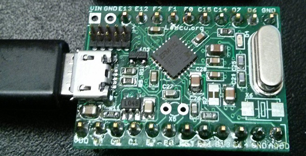
The board above is based on an Energy Micro EFM32ZG, a very small 24-pin QFN device with up to 32 kB of Flash and 17 GPIOs. As with all the bitbanged USB hacks, the differential data lines are attached directly to the microcontroller. A 24 MHz crystal is needed, but the team behind the project is working on using the internal RC oscillator instead.
The code is portable with minimal changes between other manufacturer’s Cortex M0+ chips, and with a little work, this could become a very, very cheap USB-programmable ARM dev board, something the community could certainly use.


Nitpick: it is EFM32ZG, you got the F and M swapped. You (and the original author on his page) may like to change it due to keyword-based searching.
Fixed. Thanks.
On their write-up the pinout reference with PA0 connecting to PA0 probably was supposed to be USB 5V. The sense resistor could be 10k or more to keep from damaging a 3.3V pin.
>Currently PA0 needs to connect to PC0 via a 1K5 resistor PC0 to D- PC1 to D+ of the USB port.
They connect the 1.5K pull up to PA0 so that the device can “disconnect” under software control. USB specs specified 1.5K to form a voltage divider so that one of the data lines would be a logic high. This tells the host what connection speed the device is for. 10K is a wrong value.
There are 15K pull downs for the D+/D- at the host side, so the 1.5K one one of them would form a voltage divider when sourced from a 3.3V per USB spec.
(V-USB with 5V supply requires the Zener diodes and in that case also calls for 5V pull up.)
We ended in HaD sooner than we anticipated :-) We have created a web page http://www.lemcu.org where we have details about both software and hardware. Could you please update the link in the post. Thanks.
This would be much more fun on an 8-pin LPC810. Would make a fast successor for the ATmega85.
Well, the LPC810 only has 4kb of flash. You’d end up with ery little usable space after addition a USB bootloader.
What’s the cost differential on these chips ?
This is really great! At 24 MHz there is also enough computational power to decode USB easily in realtime.
Getting this to work with an internal RC oscillator is probably not that easy. I guess it is possible to build something like a DPLL into the receive loop, but then you’d also need some kind of timing correction for the sending loop? Maybe with a fractional timer?
Things are a bit easier on AVR with RC oscillator calibration. I have not yet seen an equivalent oscillator in an ARM.
The code for this project uses software delay loops. It would be fairly easy to make those fractional. For instance, instead of doing
for(t = 0; t < 10; t++ );
you can do:
for( ; t < 1000; t += s );
t -= 1000;
With s = 100 for nominal speed.
It’s not as simple as that. Even at 24 MHz there are only 16 cycles per bit. Subtracting the instructions require to read/write usb and do housekeeping there is not a lot to work with for timing.
Some variation on the sample principe then. In assembly:
ADDS t, t, s;
BCC loop
B loop
There is the PLL multiplier/prescaler, but it is not fine gain enough for the job. The alternatives are the old way of unrolling the loop and varying the the individual bit time effectively implementing a NCO or put in a crystal.
I don’t quite understand what makes AVR RC oscillator calibration unique?
The AVR RC oscillator frequency can be adjusted in steps of less than 0.3% by software. This allows calibrating of the system clock to an external timing reference.
In the case of USB it is possible to use the USB keepalive signals to match the host clock. I have not yet seen a similar calibration register in a CM0.
The EFM32ZG has the same kind of register.
The link is broken meanwhile. The correct link is: https://www.silabs.com/community/projects.entry.html/2014/03/19/lemcusb_softwareusb-ifON
The source code is available on github: https://github.com/lemcu/LemcUSB