[Jean-Noel] is fixing a broken Lurem woodworking machine. This machine uses a three-phase Dahlander motor, which has three operation modes: stop, half speed, and full speed. The motor uses a special mechanical switch to select the operating mode. Unfortunately, the mechanical bits inside the switch were broken, and the motor couldn’t be turned on.
To solve the problem without sourcing a new switch, [Jean-Noel] built his own Arduino based Dahlander switch. This consists of three relays that select the wiring configuration for each speed mode. There’s also a button to toggle settings, and two lamps to show what mode the motor is currently in.
The Arduino runs a finite-state machine (FSM), ensuring that the device transitions through the modes in the correct order. This is quite important, since the motor could be damaged if certain restrictions aren’t followed. The state machine graph was generated using Fizzim, a free tool that generates not only FSM graphs, but also Verilog and VHDL code for the machines.
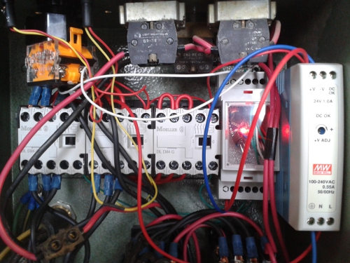
The final product is housed in a DIN rail case, which allows it to be securely mounted along with the rest of the wiring. The detailed write-up on this project explains all the details of the motor, and the challenges of building this replacement switch.


I cannot find anything related to the Dahlander motor or it’s creator on Wikipedia. Therefore it does not exist.
Look in the Dutch Wikipedia
It’s a ‘three phase asynchronous motor
Here you go (in german): http://de.wikipedia.org/wiki/Dahlandermotor
http://pt.wikipedia.org/wiki/Motor_Dahlander
Wye-delta is not for half speed, but for soft start. http://en.wikipedia.org/wiki/Motor_soft_starter
Now that’s a well documented project.
No interlocking between the star-delta contactors? Even if it’s in the program (I can’t see the code) it’s still best to hardwire the interlock as contactor faults can (and do) happen and it really f#*ks your motor. Instead of an indicator light, the auxiliary contact on each relay (they look like DILER’s so; NO, NO, NO, NC) should be used in series with the opposite contactor coil.
Indeed! Not only would this destroy the motor, you’re likely to see the contactors completely incinerate your box guts! Also, where are any thermal / magnetic overcurrent cutouts?
Would it not be a good idea to add an Emergency Stop switch, which would interrupt all three supply lines?
I noticed the same thing… if I am reading correctly, if the machine is operating in low speed mode, and there is some sort of trouble that requires an e-stop, the only choices are waiting two seconds for a shutdown push or ramping up to high speed then stop.
IMO the one button operation is probably overly simplistic. I would suggest at the very least that the button remain for “ON” operation, but a separate stop switch would be implemented that triggers an immediate shutdown, regardless of what speed the motor is running at and without delay.
Then an additional E-stop could (read: should) be implemented that physically interrupts power to the motor for emergency purposes.
I was thinking this too, I’m supprised the original setup has no e-stop solution and since the OP is modding the rig, it’d be a good oppertunity to perform a safety upgrade (especially because the system requires the user to press a single button a multitude of times before arriving at a stop sequence. There’s enough room in their for a Pilz S4 which would work on his 24V supply and an auto delayed reset which would allow the motor time to stop spinning before resetting the circuit. Also, I don’t see a motor overload arrster and the PSU should have it’s own MCB.
I have seen a relay fault on a 480 Wye-delta setup for an electric motor the size of a compact car. When it stuck the explosion slammed open the 6 foot cabinet doors faster than you could have opened then and was loud. Mechantical interlocking is very important.
“Mechantical interlocking is very important”
+1
Electrical is fine, providing it’s done using the aux contacts and not in the software.
The lack of that interlock is probably why the original controller blew up. Usually it’s the weakest part that will pop in that failure mode. The lack of an interlocked emergency stop is also pretty scary.
Why couldn’t he fix the “special mechanical switch”? I’m pretty sure It used a simple ratchet and pawl mechanism fixed to the switch shaft. He could even have made one out of wood – from one of his old wooden clogs (or is he a saboteur?!!). I suspect he WANTED to use an Arduino.