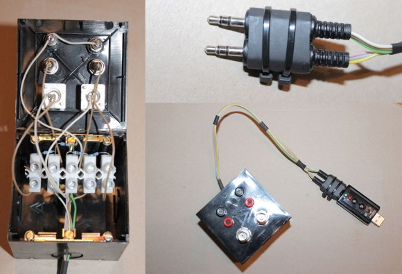
Are you interested in building a 20kHz 2-channel oscilloscope and a 2-channel signal generator for only $20 with minimal effort? Be sure to check out [Jana Marie’s] Instructable that goes over how to build this awesome tool from a cheap USB audio card.
We have featured tons and tons of DIY oscilloscopes in the past, but this effort resulted in something very well put together while remaining very simple to understand and easy to build. You don’t even need to modify the USB audio card at all. One of the coolest parts of this build is that you can unplug your probe assembly from your USB audio card, and bring it wherever your hacking takes you. After the build, all you need is [Christian Zeitnitz’s] Soundcard Oscilloscope program and you are good to go. One of the major downsides that is often overlooked when using an audio based oscilloscope, is that it is “AC coupled”. This means you cannot measure low-frequencies (including DC signals) using a sound card. Be sure to heed [Jana’s] advice and do not use your built in audio card as an oscilloscope. With no protection circuitry, it is a sure fire way to fry your computer.
What analog projects have you built around an audio interface? We have seen such an interface used for many different applications, including a few fun medical related hacks (be sure to keep safety your first priority). Write in and let us know!


Inb4 someone says you can buy a clone for 12 bucks, congratulations on missing the entire point.
I would rather stick to commonly used 1 megaohm resistor at soundcards input and 9 megaohm resistor probe (giving total input impedance of 10 Mohm). with additional approx. 2V zeners (or transils) to protect soundcard’s inputs. Ideally with isolated USB to prevent ground loops :-)
With some of the cheaper USB soundcards the capacitors responsible for filtering out DC and very low frequency AC signals are not integrated into the IC, but external and often mounted between the IC itself and the mini-jack sockets.
replace those capacitors with a jumper of some sort and the sound ‘card’ can be used for DC.
Although as Harvie.CZ mentions, some Zener diodes of correct value wired up as overvoltage shunts would be a good idea since we all tend to screw up once in a while.
Or you could buy one for $20 with a logic sniffer and two -14 to +20V inputs.
http://www.gabotronics.com/oscilloscopes/xprotolab-plain.htm
The RTL2832U dongles are worth looking at. I picked one up for $11. Aside from the obvious use for RF analysis, they can be used in direct sampling mode, bypassing the tuner. Essentially it gives you access to a 3.2msps 8-bit ADC. I’m still looking for software that will record and display the input stream…
RTL2832U has a perfectly good dual ADC just asking to be used in this manner. Im just not sure if you can disable automatic gain completely.
Another good choice is LPC4370. $6-8, 12bit @ 80Mbit and full speed USB.
http://embeddedartists.com/products/lpcxpresso/lpclink2.php
http://www.lpcware.com/content/project/Mixed-Signal-Logic-Analyzer-Oscilloscope-Lab-Tool-Solution%20
LPC4370 dev board for only 15 euro
As I mentioned on the DP site, most modern sound cards support 96ksps, and many even 192ksps. Soundcard Oscilloscope seems limited to 44ksps. GoldWave and Audacity support 192ksps.
http://nerdralph.blogspot.ca/2014/05/pc-storage-oscilloscope-and-logic.html
Ditto to what Torque says. I was using the on-board codec, so I wasn’t about to remove the input caps. In theory the drift back to 0V could be corrected for in software if it’s a real problem for you.
A lot of the sound-cards will probably have a low-pass filter on the input so even if you sample at 192K the input bandwidth will limited limited.
Just removing the input caps might not work, the input to the codec input might unipolar, i.e. something like 0-5V, not something like +/-2.5V
If you look at the screen shots on my blog the input bandwidth is well above 192khz. If there is any low-pass filter, the 6dB point would seem to be above 1Mhz. This is the on-board audio for a run-of-the-mill Acer PC with a Core i5 CPU.
Why can’t you build a voltage dependent oscillator that turns your measuring range into a sound frequency between 0-48 kHz and then you can sample it on the computer at 96 kHz. Then it’s just a simple matter of looking for the peak frequency to determine what the measured voltage is.
Though of course the effective sample rate would then depend on the voltage that you’re measuring, but that would bypass the DC problem.
OK, when I recently put together 3 wires and 4 resistors and plugged it into my sound card’s line-in I didn’t know that “I built a 2 channel oscilloscope”. I thought that I used my sound card and Christian’s great software.
Christian is duly credited in the article. And if you could benefit from this low-frequency dirt-cheap scope, likely you’re a beginner and would appreciate some instructions in building it step by step. Even as terrible as Instructables is, compared with, say, just writing it down on a web site.
The article’s handy enough just for mentioning the possibility. I’m sure Christian gets plenty of appreciation from the people who use his software, nobody’s trying to rip off his kudos.
or you could get an ARM devboard for $10 and do the same at 200khz
I spose. There ought to be a rush on really dirt-cheap USB scopes for PCs, since powerful ARM chips with the right ADCs on board are now so cheap and plentiful. All you need’s to set up the analogue front-end and you’re most of the way there. Surprised nobody manufactures them, surely there’s plenty of room in the market for a scope that does a few MHz and costs a few dozen dollars.
I’m fondly reminded of a project in an early-1990s electronics magazine, a make-your-own oscilloscope using a grid of LEDs as the display! Must have been useful enough, plenty of people wrote in about them. You could pretty much make one with a counter IC driving the horizontal and a bargraph IC for the vertical. This was just before everyone switched over to using microcontrollers.
I think the cypress Arm mcu has a 1mhz DAC, and they’re only $1…
Cypress 32bit PSoC-5 for $1? very much doubt that, unless you meant $10
for $1 you can have old crusty custom arch psoc-1
DSO nano
http://www.seeedstudio.com/wiki/DSO_Nano
is build around 1Msps 12Bits ADC integrated inside STM32F103VBT6. Its basically ARM chip + little front end + lcd.
Chip alone is $3
For scopes of this type will point out that there is an excellent free program (although not open source) http://www.sillanumsoft.org/index.htm
Thanks for this link. I have some “legacy” hardware that runs win-98
nicly and the versions of this may let me set up a strictly off-line
box for 98.
That would allow me to install a really stripped down version of 98 and should hopefully let the O-scope program run pretty well.
The stripped install worked well for an off-line video and CD editing / media box.
Any concern about the noise factor on those cheapo USB soundcards? I have found them so poorly constructed that I can’t use them for ham radio use at all…
uhhh…. Or, or, and hear me out now, you can save the arduino for something
an arduino could be better suited for, and take a 1/8″ phono jack cable, cut off
one end, and solder alligator clips to the wires, plug it into your laptop, and run
Audacity. There ya go. Signal generator at headphone jack, oscilloscope (with
recording and software filtering, etc) on microphone side. Then use the arduino
for like an mp3 player or something.
The sampling rate of a sound card is a bit too low, up to 192 kHz only. Bandwidth up to 96 khz. If you sample a 50khz sine wave, you only get 4 points per cycle. Quite difficult to render a correct sine shape. There is a trialware called Multi-Instrument (from http://www.virtins.com) claiming to be able to do equivalent time sampling, thus increase the samples per cycle dramatically? Without any modification of the sound card hardware, not sure how they made it?.